This is a continuation of my attempt to get Titan Overdrive 2 working in my Genesis emulator. It will be more technical than Part 1 as fixing the remaining effects requires getting into low-level details of how the Genesis VDP functions, which these effects depend on.
Who Needs Dedicated Hardware for 3D?
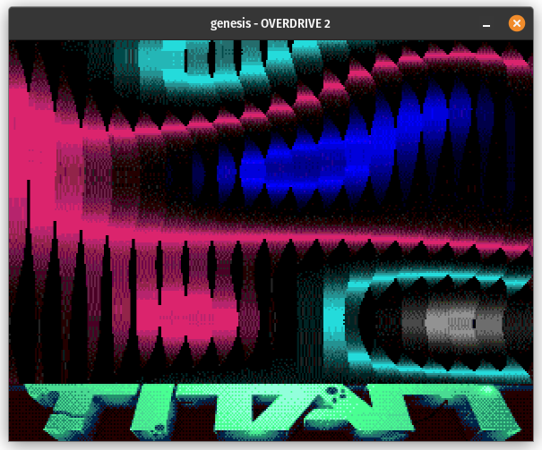
Now we get into issues that are a lot less easy to fix. This is a (glitched) 3D animation of a textured cube:
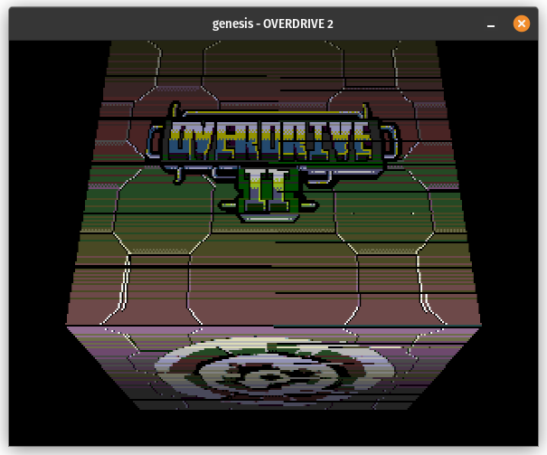
This effect depends on some very precise details of how the VDP’s sprite hardware works. As an overview, the Overdrive 2 documentation describes sprite processing in 4 phases:
- Phase 1: Scan the sprite attribute table to determine which sprites overlap the target line, based purely on Y position and vertical size
- Phase 2: Fetch non-cached sprite attributes from VRAM. These include X position, palette, priority, and horizontal/vertical flip flags
- Importantly, the cached sprite attributes (Y position and size) are also locked in during this phase
- Phase 3: Fetch sprite tile data from VRAM and render the sprite pixels into a 320-pixel-wide line buffer
- Phase 4: Merge the sprite line buffer with the other planes to produce displayed pixels
Phase 1 occurs 2 HBlank periods before the target line, Phase 2 occurs while rendering the line before the target line, Phase 3 occurs during the HBlank period before the target line, and Phase 4 occurs while rendering the target line.
One of the demo’s devs describes what they did during this scene here. The cube rendering depends on correctly emulating the timings of Phases 1 and 2, as well as how the VDP handles a sprite’s Y coordinate changing to be out-of-range in between Phase 1 and Phase 2. The sprite is still rendered despite going out-of-range, but the row within the sprite is calculated using the updated Y coordinate rather than the old one, and only the lowest 5 bits of the difference are used in case the difference is negative or greater than 31.
Before I encountered this I wasn’t even emulating different parts of sprite processing occurring at different times, so first I needed to do that. In order to avoid breaking the fix for the “your emulator suxx” screen in Overdrive 1, I do Phase 1 at the end of HBlank when I know how many pixels the display was disabled for, but I do the sprite scan using sprite attribute values that were latched when HINT was generated (slightly earlier in the line). This is actually necessary for Overdrive 2 because shortly after HINT it changes the sprite attribute table address and immediately starts writing new sprite Y positions that are supposed to take effect for Phase 2 but not for Phase 1.
Next is Phase 2, where the VDP locks in all of the sprite attributes for every sprite that was scanned during the previous HBlank. In actual hardware, this is performed in parallel with rendering the scanline before the target scanline. I emulate this by doing the sprite attribute fetch in bulk at the very end of the rendering period, after all of Overdrive 2’s sprite Y coordinate writes but before it changes the sprite attribute table address during HBlank. This seems to work.
Finally is the actual sprite pixel rendering (Phases 3 & 4 combined), which works pretty much as it did before only with the modified sprite row calculation in case the sprite’s Y position is no longer in-range of the target scanline. I did take the opportunity to overhaul how sprites are merged with the other layers - instead of searching for the first non-transparent sprite pixel at each position, I render all of the sprite pixels into a line buffer similar to what actual hardware does, and then when merging with other layers I just do a lookup into the line buffer.
The line buffer rendering is pretty simple. At the start of each line, fill the line buffer with pixels with palette/color/priority all set to 0. Iterate through the sprites in the order they were scanned, and then for each sprite, write all of that sprite’s pixels into the correct positions in the line buffer if the pixel currently at that position in the line buffer is transparent (color == 0). This has the same effect as what I was doing before but is both simpler and more efficient. It also more gracefully handles the Overdrive 2 logo screen without needing to special case positions where all sprite pixels are transparent.
After pretty much completely rewriting my sprite processing and rendering code, the effect is fixed:
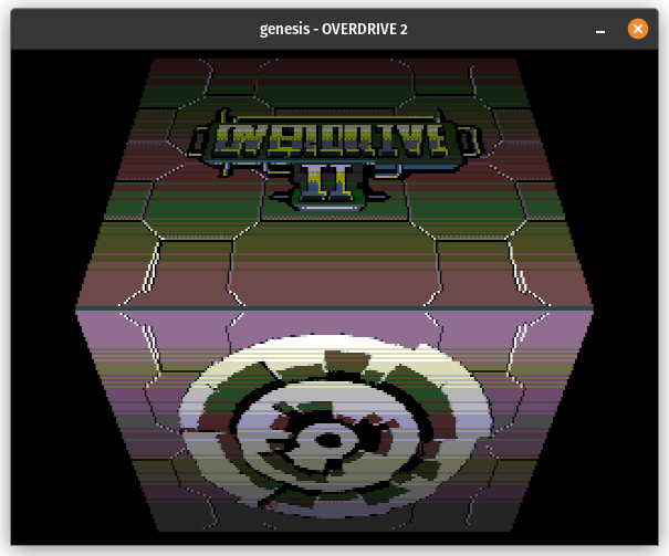
Perfect Timing
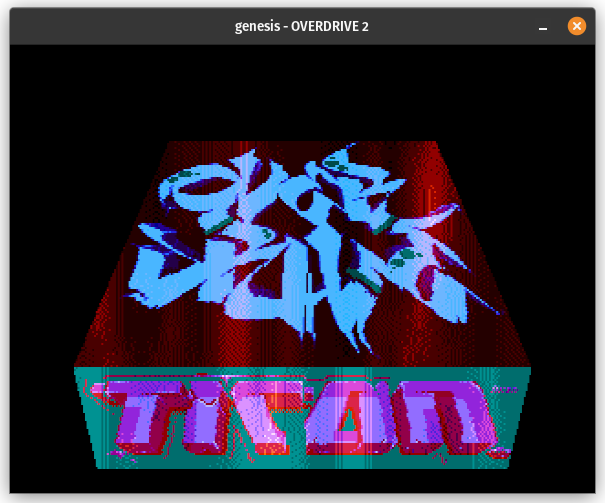
The plasma twisters effect:
If it’s not obvious, all of those horizontal black lines aren’t supposed to be there. The fact that they’re there means that my timing is off.
This is probably the hardest effect in the demo to emulate properly because it requires nearly perfect VDP FIFO queue timing or else you’ll get horizontal black lines as seen above. The code is not syncing to HINT or the HV counter or anything of the sort; it’s simply writing values to VSRAM (vertical scroll RAM) as fast as the VDP will let it. The black lines occur because after every 20 values written, the code disables display and does a DMA to copy the next 20 values. If timing is correct, this will always happen during HBlank. If timing is not correct, well, see above screenshot.
I described a bit of how the VDP FIFO queue works in my post on emulating Overdrive 1, which has several effects that depend on FIFO queue timing being in the right ball park. This plasma twisters effect demands even more precise timing.
Part of the trick for this effect is based on where exactly the VDP’s external access slots are placed within the scanline. In H40/320px mode, there are 18 external access slots per scanline, but only 1 of them appears to be during HBlank. 15 are spaced throughout active display, 2 occur roughly at the end of active display / start of HBlank, and then there’s 1 about halfway through HBlank.
Once display is re-enabled after the DMA, the code performs 20 VSRAM writes as rapidly as it can and then immediately disables the display again. This will happen when the 20th write enters the FIFO queue, or equivalently after 16 writes have been popped from the queue via external access slots. Assuming that the code misses the external access slot halfway through HBlank (which it will if timing is correct), the 16th write will get popped in one of the external access slots right at the start of the next HBlank period, at which point disabling the display will have no visible effect because all 320 pixels for the line have already been rendered.
My existing implementation of FIFO write delay did some floating-point math and assumed that external access slots were evenly distributed throughout the scanline, which obviously does not work for this particular effect. I ended up rewriting my implementation to precisely track when external access slots are crossed:
|
|
Now, this is a bit sketchy because my emulator is really not set up to do extremely precise timing like this. I execute 68000 instructions atomically rather than tracking the exact cycles at which bus reads and writes occur. Despite that, this seems to work? No more horizontal black lines:
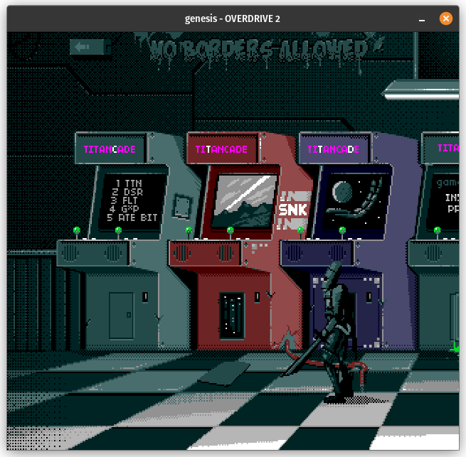
No Borders Allowed
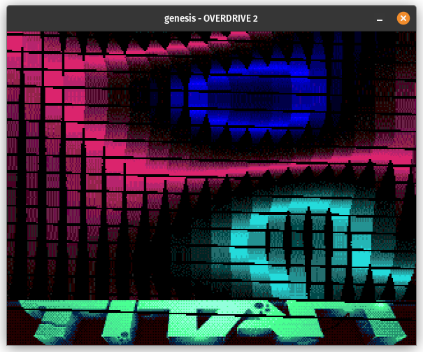
The arcade scene currently looks like this:
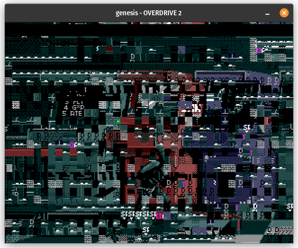
The biggest issue is an undocumented (and probably unintended) behavior related to switching between V28 mode and V30 mode at a specific point in the frame. The code starts each frame in V28/224px mode, switches to V30/240px mode shortly into the frame, and then switches back from V30 mode to V28 mode between scanlines 225 and 239. This apparently causes the VDP to “forget” to end the frame properly, which among other things means that it continues processing horizontal interrupts as if it was still actively rendering.
Simply implementing the fix to continue processing HINTs if end-of-frame was “forgotten” makes the scene look a lot better, and also makes it run at the correct speed (it was way too slow before the fix):
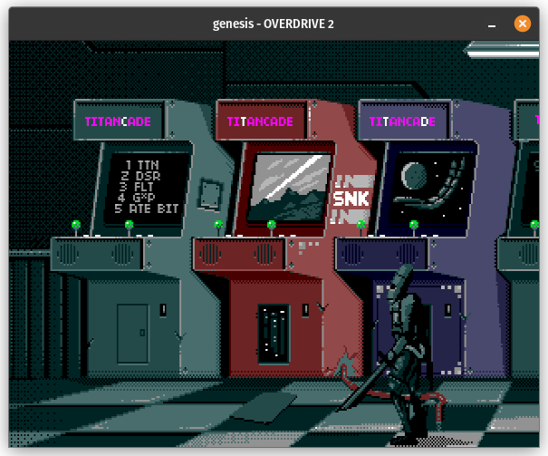
Of course, if you’ve watched the hardware recording, you know that the most important piece of this scene is still missing: the fact that it’s rendering in the borders! That is not supposed to be possible!
To define what a border is here, the PAL Mega Drive renders 347x294 frames in H40 mode, but it normally only renders graphics in the center-ish 320x224 pixels (V28 mode) or 320x240 pixels (V30 mode). The remaining pixels are the border and they normally always display the backdrop color. Most of these border pixels were expected to be hidden by TV overscan.
My first major challenge here was getting my VDP to render the borders at all instead of assuming that row 0 + column 0 in the frame buffer always corresponds to the top-left corner of active display. I also wanted to make it configurable whether the borders display rather than always displaying them. Nothing super technical, just lots of details to get right, and forcing a separation between the concept of raster line (which line of pixels to display from the background and sprite layers) and frame buffer row.
For this particular scene, rendering the vertical border isn’t too difficult. When the VDP “forgets” to end the frame due to the V28/V30 switch, it simply continues rendering normally inside the vertical border area. For the bottom border, raster line continues counting up from the end of active display. For the top border, the bottom line of the border is raster line 511 since the VDP uses a 9-bit counter for raster line.
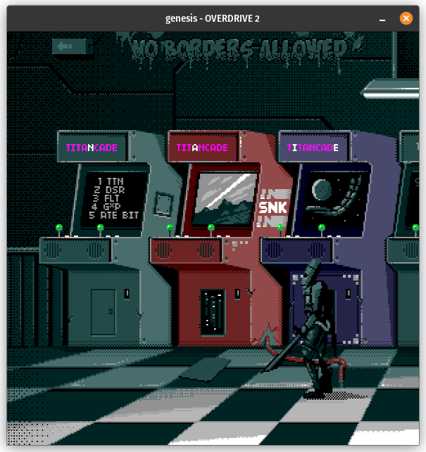
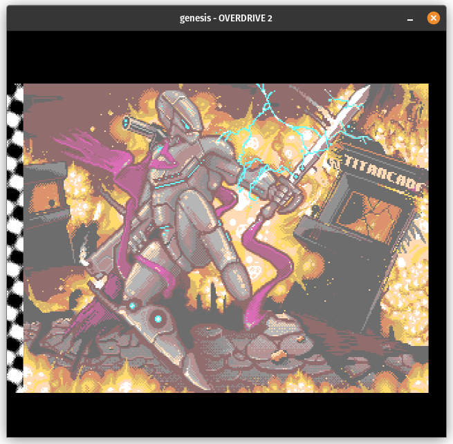
Implementing this gets the “no borders allowed” text to display (and makes the screen much taller):
The horizontal border is trickier. Rendering non-garbage graphics in the horizontal border is only possible by using the VDP debug register and it depends on precise details of how the VDP operates.
If the sprite plane is forced on or used as the mask plane, all pixels in the horizontal border will display color 0 in CRAM. Sprite pixels never display in the horizontal border. …At least, not as part of sprites.
If one of the two background planes is forced on or used as the mask plane, things get more complicated. First of all, the VDP naturally renders the background pixel immediately to the left of active display, and it will render the full column containing that pixel (“column -1”) which could be as many as 16 pixels to the left of active display depending on horizontal scroll value. It will also render the entirety of the final column rendered during active display, which could be as many as 15 pixels to the right of active display. These pixels are normally hidden by the border but the debug register makes it possible to display them (from one of the two backgrounds).
For the remaining border pixels, the VDP takes whatever byte it happened to be fetching at the time, interprets it as pixel color data, and displays it using the color palettes from the last 2 tiles of background B from the previous line. For background A this data ends up being a combination of sprite pixel data and H scroll data, and for background B this ends up being only sprite pixel data (though from different sprite tiles).
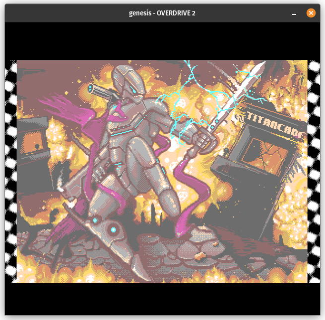
Now, for this scene, it isn’t actually necessary to emulate all of that. Just rendering more pixels from the forced background in the border works well enough:
However…
Strange Bugs in the Borders
The fade-out from the arcade scene currently looks like this:
That black-and-white pattern in the left border is supposed to be in all four borders. Also, some of the other screens have junk in the borders that isn’t supposed to be there.
Fixing the right border (and the junk in other screens) requires implementing the behavior I described above, where the VDP renders specific sprite pixels in the edges of the border when one of the two backgrounds is either forced or used as the mask plane.
This ended up being quite tricky with how my VDP code was structured, primarily because rendering the right border requires knowing which sprite tiles will be fetched for the next raster line. My VDP does sprite tile fetching and line buffer rendering as part of the routine that renders a line of pixels to the frame buffer. I ended up adjusting my line rendering routine to also render the previous line’s right border if horizontal border rendering is enabled, which is a bit messy but works:
I did discover an unrelated bug while implementing this, which is described here. Turns out that in per-two-cell vertical scrolling mode, column -1 always uses the last V scroll values from VSRAM in H40 mode and always uses V scroll values of 0 in H32 mode. Overdrive 2 depends on this to not display junk in the left border on some screens, and apparently the game Gynoug depends on this to render correctly within active display due to combining per-two-cell vertical scrolling with fine horizontal scrolling (H scroll value % 16 != 0).
Now for the vertical borders, which on this screen use the debug register to force background A rather than the V28/V30 switch trick. When that trick is not used, the vertical borders contain what the Overdrive 2 documentation describes as “strange bugs”.
This effect depends on how exactly the VDP’s VRAM chip stores data physically, and how it operates when the VDP is not actively fetching data.
VRAM is physically organized into 256 rows that each contain 256 columns, with each column containing color data for 2 pixels (for bytes that are used as tile data). However, the mapping from VDP VRAM address to physical address is not completely linear; going by VRAM address, each row contains 64 4-column groups that are each separated by 1KB in the VRAM address space. There’s more detail on this here.
Whenever the VDP fetches from VRAM during rendering, the chip’s serial access port remembers what row was requested and begins to repeatedly cycle through the 256 columns in that row until the VDP requests a different VRAM address. Before the vertical border starts, the last VRAM fetch as part of rendering is for the 4th sprite tile that would have been rendered on raster line 224 (one past the last line of active display). This means that during VBlank, the chip is repeatedly cycling through the columns that are in the same row as that 4th sprite tile, specifically in the tile row that would have rendered on line 224. (Unless fewer than 4 sprite tiles would have been fetched for line 224, in which case the VDP re-fetches whatever address was fetched the last time at least 4 sprite tiles were fetched for a line.)
Inside the vertical border, the VDP interprets the bytes returned from the VRAM chip as pixel data and simply displays them using the last color palettes that were used during rendering. Normally all of these pixels are hidden by the border, but forcing one of the background planes using the debug register makes them visible.
The VDP displays 8 consecutive columns (16 pixels) out of every 32 columns read, excluding the period between the right border of one line and the left border of the next line where it does not display anything. In total the VRAM chip goes through 840 columns per line, 2 per pixel clock. This ultimately results in the VDP cycling between 4 different 128-pixel patterns on a line-by-line basis, with each pattern getting shifted left by 16 pixels each time it’s repeated.
This was tricky to emulate. First getting the pattern to display correctly at all in the vertical borders by getting the per-pixel and per-line VRAM strides correct while taking into account that the VDP skips 24 out of every 32 bytes, and then some trial-and-error to figure out the line and pixel offsets necessary to get the vertical border patterns to align properly with the horizontal border patterns. It was certainly much easier to think of the accesses in terms of 4-byte groups separated by 1KB as the Overdrive 2 documentation describes.
To be more concrete, this is how I calculate the starting address for each line:
|
|
And this is how I iterate pixel-by-pixel, where pixel 0 here is the left edge of the left border:
|
|
After all that, lo and behold:
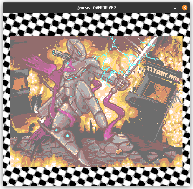
Phew. That was a lot of work for an effect that lasts for less than a second…
There is one other quirk that’s required to avoid visual glitches on some other screens, which is that raster line 511 (the line immediately before active display) renders somewhat normally when the debug register is used despite technically being inside the vertical border. It will contain a strip of pixels from whichever plane is set in the debug register.
Wait, What About That One Scene?
The 3D scene at the end is certainly one of the most impressive effects in the demo:
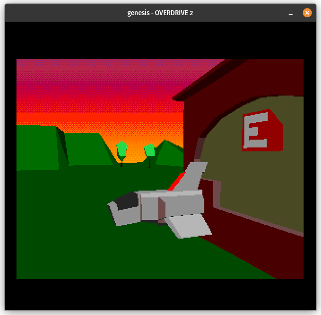
However, this is actually one of the easiest parts of Overdrive 2 to emulate! It’s not doing anything crazy with the VDP hardware, it’s just a really efficient software renderer written in 68000 assembly.
And That’s It
With that I believe I have the entire demo working properly, although there may be minor differences from hardware that I haven’t personally noticed. I also don’t emulate CRAM dots because my emulator doesn’t have a high enough level of timing accuracy for 68000/VDP interactions or VDP DMA to be able to render those in the right spots.
Was it worth it? Yes, I think so! While my VDP now has lots of code that exists pretty much solely to get Titan Overdrive 1 & 2 working (mostly 2), I found and fixed a number of more general bugs along the way, some of which affected officially licensed games. It’s also been educational as it forced me to learn quite a bit more about how the VDP works, well beyond what officially licensed games depend on.
I’ll end with links to the demo and my emulator: