In my last post I described an enhancement that an SNES or PS1 emulator can implement to improve audio quality in some games. Since then, I noticed that Sega CD games that use its PCM sound chip have pretty poor audio quality in my emulator - the audio output sounds very noisy and aliased. I wondered, is it possible to improve this using a similar technique?
Spoilers: The answer is yes! Though there are some interesting differences in the details.
This started as a post describing both the sound chip itself and the enhancements/improvements I implemented, but it got too long, so I’m splitting it into two parts. This first part is an overview of the sound chip and how to emulate it at a basic level. The second part will cover what I did to improve audio quality.
Sega CD
The Sega CD, or Mega CD in Japan and Europe, was the first of two console add-ons that Sega produced for the Genesis / Mega Drive. It’s widely viewed as a commercial failure, but it did fare much better than the second Genesis add-on, and in the US it sold almost as well as the Saturn. Granted, that’s more an indictment of the Saturn than an accomplishment of the Sega CD.
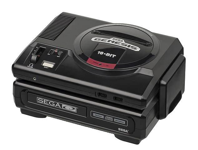 Model 1 Genesis + Sega CD; image from Wikipedia
A full overview of the Sega CD hardware and how games utilize it in combination with the Genesis hardware is beyond the scope of this post, but at a high level, Sega CD adds the following components that all run in parallel to the Genesis hardware:
- 1x CD-ROM drive and a CD-ROM decoder chip, with 16 KB of RAM for buffering CD-ROM sectors
- A second Motorola 68000 CPU clocked at 12.5 MHz (roughly 63% faster than the 7.67 MHz Genesis CPU)
- 512 KB of “PRG RAM” (program RAM) for the new 68000
- 256 KB of “word RAM” shared between the Genesis side and Sega CD side, with manual handoff/bank swap logic
- This is the primary mechanism for transferring data between the Sega CD hardware and the Genesis hardware
- 8 KB of battery-backed “backup RAM” for storing save files
- An affine transformation graphics chip that can perform hardware-accelerated affine image transformations within word RAM
- This is essentially a more generalized version of what SNES Mode 7 can do, though displaying the transformed images requires copying them into Genesis VRAM which has bandwidth limitations
- Ricoh RF5C164, an 8-channel PCM sound chip capable of playing 8-bit PCM samples from 64 KB of attached PCM RAM
- A few other miscellaneous minor features, like a hardware timer and font rendering functionality
The Genesis cartridge slot is generally unused, but Sega CD does support an optional 128 KB battery-backed RAM cartridge for storing more save files than can fit in the console’s 8 KB of internal memory. (The hardware actually supports RAM cartridge sizes up to 512 KB, but only 128 KB cartridges were ever officially produced.)
There are also at least two Genesis cartridges that are designed to be used with Sega CD, Flux and Wonder Library. These cause the hardware to boot in an alternate mode where it boots from the cartridge instead of the Sega CD BIOS ROM, and the Genesis-side memory map is slightly altered to support this. (My own emulator doesn’t currently support this behavior, known as “Mode 1” in Sega’s official documentation.)
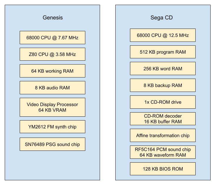 Major hardware components across Genesis and Sega CD
Yes, Sega went a little crazy with the hardware for what was just a Genesis add-on. If it had its own video display hardware and controller I/O ports, it could have been a standalone console! The affine transformation chip in particular was really not necessary, though a few games did utilize it for cool graphical effects - Batman Returns and SoulStar are two notable examples.
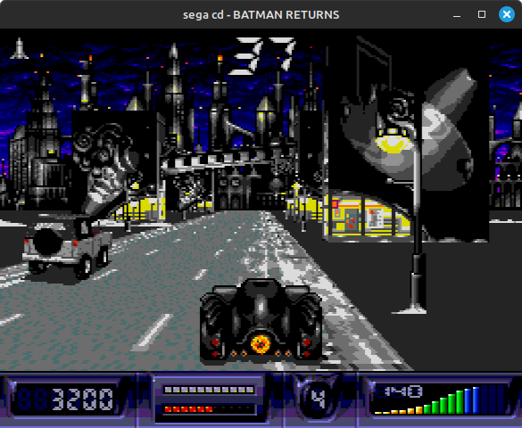 Batman Returns heavily uses the affine chip for scaling/rotation during its driving stages
For comparison, the PC Engine CD really only added a CD-ROM drive + decoder chip, a single-channel ADPCM sound chip, and a lot of additional RAM. PCE CD didn’t add an additional CPU or any additional graphics functionality, nevermind things like font rendering.
All of this new hardware makes the Sega CD rather difficult to program for. The main problem is that most of the new hardware is only controllable by the Sega CD 68000, but the Sega CD 68000 can’t directly access any of the Genesis hardware, so the two 68000s need to coordinate to make anything useful happen. Both 68000s can access word RAM, but the Genesis side and Sega CD side can’t access the same sections of word RAM simultaneously, so they still need to coordinate around word RAM exchanges. The Sega CD provides a set of communication ports to facilitate this coordination, but it’s inherently complex to program for a multi-CPU system where different parts of the system are accessible to different CPUs.
This is unfortunately reflected in some of the released Sega CD games, and this led to some rather painful debugging experiences when I was first developing my Sega CD emulator. A number of games and at least one BIOS version have sloppy inter-CPU communication code that only accidentally avoids race conditions due to the speeds and timings of the various processors involved. I honestly wouldn’t be surprised if Silpheed still randomly freezes in my emulator due to a race condition in its word RAM handoff code, though I haven’t personally seen it happen since I made some timing improvements.
The rest of this post is going to focus on the Sega CD’s PCM chip.
Four Sound Sources
Sega CD games have four ways of playing audio, two through the Genesis hardware:
- Yamaha YM2612 FM synthesis sound chip (aka OPN2)
- Texas Instruments SN76489 PSG sound chip (same sound chip as Master System and Game Gear; the Genesis has one too)
And two through the Sega CD hardware:
- Ricoh RF5C164 PCM sound chip
- CD digital audio tracks (CD-DA)
Why does the Sega CD include a PCM sound chip in addition to CD audio playback?
Well, CD-DA has excellent audio quality (stereo 16-bit samples at 44100 Hz), but it comes with two huge limitations.
First, the drive can only play one track at a time, and seeking to a new location can incur a long delay before the drive starts playing. This makes CD-DA rather useless for in-game sound effects.
Second, games can’t read data from the CD-ROM while the drive is playing an audio track. If a game wants to read data then it needs to pause audio playback, seek to the data location, read the data, then seek back to the audio track and start playing again. This will cause an audible interruption in audio playback, and the interruption could last for several seconds depending on what the game is doing.
For some games, this second limitation isn’t a big deal. They can load all the game data they need into the Sega CD’s 768 KB of combined RAM + the 64 KB of Genesis working RAM, start up an audio track for high-quality music, and then operate purely from RAM without touching the disc again until e.g. loading a new stage. If we briefly pretend that the PCM chip doesn’t exist, these games can play all of their sound effects using the two Genesis sound chips, the YM2612 and the SN76489.
For other games, not being able to read from disc while playing sample-based audio is a non-starter. For example, if a game is playing a fully animated cutscene, it’s unlikely that it can fit all of the cutscene’s graphical assets into RAM - it needs to stream assets from disc as the cutscene plays, and so it needs some mechanism other than CD-DA to play the cutscene audio (which is probably also streaming from disc, interleaved between video data).
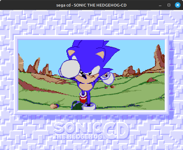 Sonic CD's opening cutscene; video frames are streamed from disc
Some games work around this by making the cutscene graphics and animations simple enough that an entire scene’s graphical assets can fit in RAM. Snatcher is one example - it plays a (very good) CD-DA track over its opening cutscene. This is not a realistic option for anything that plays FMV cutscenes though.
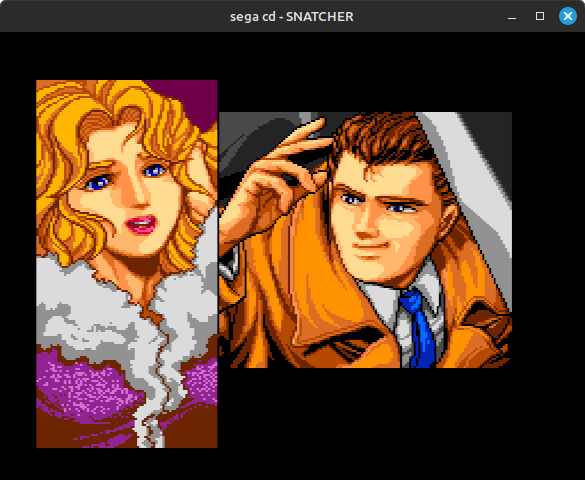 Snatcher's opening cutscene; all graphical assets are loaded into RAM before the scene starts
The YM2612 and the SN76489 are fine for music and sound effects, but they’re not suitable for playing high-quality sample-based audio. It’s possible to play 8-bit PCM samples through the YM2612’s DAC channel, and this is how standalone Genesis games play voice samples (as well as how demos like Bad Apple play sample-based music), but the quality is generally not great. It’s also very difficult to stream audio samples from the CD-ROM to the YM2612 with even remotely reliable timing due to how the Genesis hardware and the Sega CD hardware are split, plus the fact that the YM2612’s DAC channel doesn’t queue or buffer samples - it always outputs the most recently written sample.
 Bad Apple (Genesis)
For a bonus option, there’s the trick that some Master System and Game Gear games use where they play 4-bit PCM samples through the SN76489 by setting the tone channels to an ultrasonic frequency and rapidly adjusting their volumes, but…uhh…
…The quality is not really there, to say the least. And also the same difficulties apply regarding streaming samples from the CD-ROM.
Hence, the Sega CD has a PCM sound chip. This chip is specifically designed for playing sample-based audio, and the Sega CD 68000 can control it directly without needing to coordinate with any of the Genesis hardware. Games can even use CD-ROM DMA transfer to copy audio samples directly from buffered CD-ROM sectors into PCM RAM. The PCM chip’s audio quality is much lower than CD-DA, but it’s the next best option for sample-based audio in cases where games can’t use CD-DA.
Here’s part of the music that Sonic CD plays through the PCM chip during its intro cutscene (pictured above):
For a quality comparison, here’s a snippet from the CD-DA version that’s used elsewhere in the game:
(As an aside, each of these 4 sound sources outputs at a different sample rate: the YM2612 at about 53267 Hz, the SN76489 at about 223721 Hz, the RF5C164 at about 32552 Hz, and CD-DA at 44100 Hz. One of several challenges in Sega CD audio emulation.)
RF5C164
The RF5C164 is an 8-bit PCM sound chip. It plays uncompressed 8-bit PCM samples from its attached PCM RAM, 64 KB in Sega CD. Games can optionally compress the samples on disc and decompress them in software, though this prevents using DMA to copy the samples into PCM RAM - the game will need to manually write the decompressed samples into PCM RAM.
Games could also generate audio samples in software and use the PCM chip to play the software-generated samples, but I don’t know if any games do this in practice. I don’t think there’s much of a need given the large storage capacity of CD-ROM combined with the chip having 8 different channels that can play different samples simultaneously.
This chip supports no envelope functionality, only fixed volume multipliers set by software. This combined with the lack of compression makes it significantly simpler than the ADPCM sound chips in the SNES and PS1. However, the raw sample data takes almost twice as much space compared to those ADPCM encodings, and the quality is not necessarily better - 8-bit quantization tends to add a lot of audio noise.
One thing to note is that this chip’s PCM format is not standard 8-bit PCM, either signed or unsigned! It uses a sign+magnitude format where the highest bit is a sign bit (1=positive, yes really) and the lowest 7 bits are the magnitude (0-127). Also, 0xFF is a reserved value used for looping, so the sample range in practice is -127 to +126 with two different representations of 0.
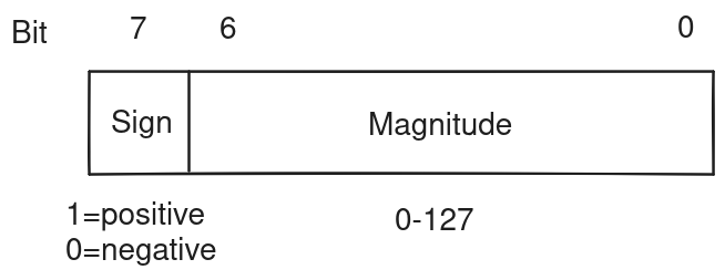 RF5C164 PCM sample format
The RF5C164 has 8 PCM playback channels. Software writes 8-bit sample data into PCM RAM, points a channel at the start of the sample data, configures the channel’s “address increment”, and then starts the channel. If the channel ever encounters an 8-bit sample value of 0xFF, it interprets that as a “loop end” marker and immediately jumps to a loop address previously configured by software. The chip does not support automatic loops based on flags like the SNES and PS1 sound chips do - software must always manually set the loop start address, and it must manually mute or disable channels as needed.
That “address increment” is a 16-bit value that represents a fixed-point decimal number with 5 integer bits and 11 fractional bits. Sega’s official documentation refers to the two 8-bit registers used to configure this value as “FDH” and “FDL” without explaining what “FD” stands for (frequency delta maybe?), but this value is essentially the sample rate on a scale where 0x0800 is equal to the PCM chip’s native sample rate.
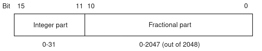 RF5C164 sample rate format (unit = multiples of 32552 Hz)
Sample rate is applied similarly to how it is in the SNES APU and PS1 SPU. The sound chip itself always outputs samples at the same sample rate, approximately 32552 Hz (12.5 MHz / 384), but channels can progress through samples at a faster or slower rate than that. On each 32552 Hz clock, the sound chip mixes the samples that each active channel is currently pointing at to produce an output sample.
(Note that in reality, the sound chip is clocked at 12.5 MHz and it takes 384 clock cycles to do all of the work that it needs to do in order to generate an output sample, but that detail is not really important for emulation given how games use the chip.)
Each channel has an internal 27-bit “current address” register that represents a fixed-point decimal number with 16 integer bits and 11 fractional bits. Once per 32552 Hz clock, the sound chip adds each channel’s sample rate (5.11 fixed-point) to its current address register (16.11 fixed-point). For output sample generation, the current address register’s 16 integer bits are interpreted as a PCM RAM address, and the chip reads the sample at that location in PCM RAM. If it read out a 0xFF loop end marker, it changes the current address to the channel’s loop start address and immediately reads a new sample from the beginning of the loop.
The chip technically supports sample rates ranging from slightly less than 16 Hz (0x0001) to slightly less than 1041651 Hz (0xFFFF), but games seem to typically use sample rates between 12000 Hz and 32000 Hz, and more commonly on the lower end of that range. I suspect that low sample rates were common due to the low size of PCM RAM - 64 KB is barely enough to hold two seconds’ worth of samples at the chip’s native sample rate of 32552 Hz.
For volume, the chip supports an unsigned 8-bit master volume - “envelope” in official documentation even though it’s a constant volume - and unsigned 4-bit L/R panning volumes, both per-channel. Software needs to set these manually. These are applied as simple integer multipliers, and then the chip drops the lowest 5 bits after the multiplication, so the final volume-adjusted samples are effectively signed 15-bit (signed 8-bit + 12 - 5).
The sign bit is applied after applying volume and truncating the lowest 5 bits, which means that negative samples are rounded towards 0 rather than away from 0. There isn’t an audible difference compared to applying sign bit before volume though.
Channels are mixed by summing these signed 15-bit samples across all 8 channels, and the chip clamps the final result to signed 16-bit.
Emulating It
Emulation for a single channel is pretty straightforward. We can make a PcmChannel struct to store per-channel settings and state, that looks something like this:
|
|
The channel start address is actually only configurable as an 8-bit value - the low byte is always 0. Let’s assume that start_address here is the equivalent of u16::from_be_bytes([st_register, 0x00]).
Let’s make a method to clock the channel, which should be called once every 384 Sega CD CPU clock cycles:
|
|
Clocking the chip itself just means clocking every channel and generating a stereo audio sample:
|
|
Panning and volume adjustment can be performed while mixing the channel outputs, which could look something like this:
|
|
That’s pretty much the gist of it, aside from all the code to handle the I/O ports and registers. This is not a complex sound chip.
Where the SNES APU and the PS1 SPU both perform interpolation when a channel is partway between samples in order to create a smooth sound, this PCM chip does not appear to do anything of the sort. All documentation I can find suggests that it performs no interpolation whatsoever, which means it’s doing the equivalent of nearest-neighbor interpolation. This is practically guaranteed to introduce audio aliasing when resampling to the chip’s 32552 Hz output rate from other sample rates, and…well…
The Problem
Lunar 2: Eternal Blue plays nearly all of its music and voice acting through the PCM sound chip.
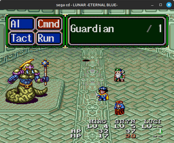 Lunar 2's first boss fight
Here’s part of the boss theme:
This was recorded in my emulator. If you’re using headphones or high-quality speakers, this recording probably sounds terrible. It certainly sounds terrible to my ears! There’s a ton of noise and aliasing. It’s almost a Game Boy Advance-like sound - a system infamous for its poor sound quality, and which also happens to have an 8-bit PCM sound chip that does nearest-neighbor resampling…though GBA has other sound quality problems on top of that.
From logging the state of the PCM chip here, all active channels are playing with a sample rate of 0x0400. In the 5.11 fixed-point decimal format, this represents 0.5, which means that every channel is playing at exactly half the chip’s native sample rate of ~32552 Hz: approximately 16276 Hz. In other words, every PCM sample is playing exactly twice.
Intuitively, you might think this would work fine, given that each channel is playing at an exact integer divisor of the output sample rate. In practice, it very much does not work fine! …At least not with the way I’m currently emulating this chip.
This was much less of an issue for the Sonic Boom recording up above because it uses a sample rate of 0x080C / ~32743 Hz, which is extremely close to the chip’s native sample rate of 32552 Hz. There’s a lot of popping in that recording, but that’s a separate issue caused by how the game uses the PCM chip.
To Be Continued
The next post will go into more detail on what exactly is going wrong here, followed by what I did to improve things - there’s more than one solution! (One of them is probably obvious if you’re familiar with Genesis audio.)
For a preview, here are two different approaches to slightly cleaning up that Lunar 2 boss theme:
Useful References
- Mega CD official documentation: https://segaretro.org/Mega-CD_official_documentation
- In particular, RF5C164 documentation: https://segaretro.org/File:MCDHardware_Manual_PCM_Sound_Source.pdf
- Sega CD PCM format: https://segaxtreme.net/threads/sega-cd-pcm-format.13267/#post-182816
- Sega CD Mode 1: https://gendev.spritesmind.net/forum/viewtopic.php?t=1018