This is the second of two followups to my post on the Sega CD PCM chip. Where the last post described a way to improve audio quality by applying an audio filter to final mixed PCM chip output, this post will describe an audio enhancement that improves audio quality by changing how the emulated chip itself generates samples. This is very similar to what I described in this post on the SNES and PS1 sound chips, though the details are a bit different since actual hardware appears to perform no interpolation rather than overly soft interpolation.
Better Ways to Upsample Audio
Let’s start with the graphs from the previous post that demonstrate the problem with duplicating samples / nearest-neighbor interpolation, which is how the Sega CD’s PCM chip interpolates from individual channels’ sample rates to 32552 Hz (at least as far as I’m aware).
Here are the original 11 samples:
 Samples of a sine wave
Here’s the nearest-neighbor upsampled version:
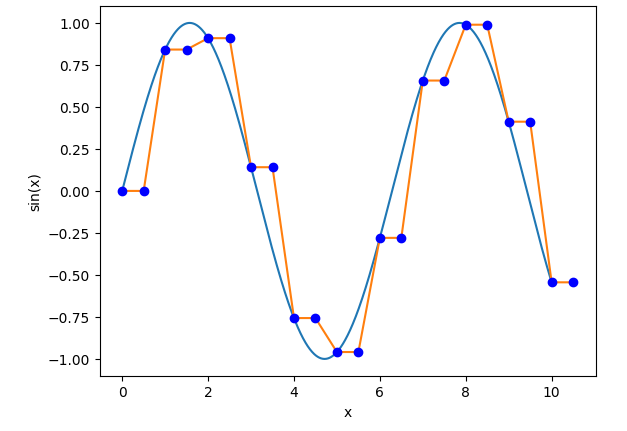 2x upsampling via nearest-neighbor interpolation
The last post stopped there and shifted to the topic of digital signal filtering. Let’s go back and continue this thread: what are some better ways to upsample an audio signal?
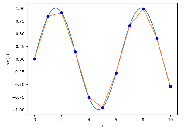
After nearest-neighbor interpolation, the next-simplest upsampling method is 2-point linear interpolation, i.e. averaging the two adjacent samples:
 2x upsampling via 2-point linear interpolation
This works significantly better than nearest-neighbor, but there are still some noticeable errors compared to the original sine waveform.
Next, I’m going to use the Hermite interpolator implementations from this paper: https://yehar.com/blog/wp-content/uploads/2009/08/deip.pdf
Let’s try doing 4-point cubic Hermite interpolation, applying this formula with x=0.5 (halfway between samples):
|
|
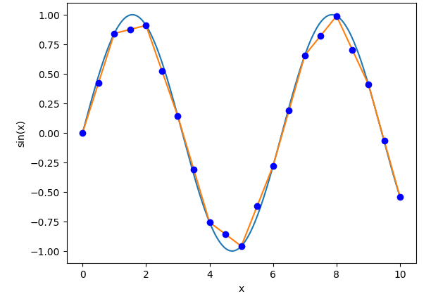
That produces this:
 2x upsampling via 4-point cubic Hermite interpolation
That’s not bad! Not perfect, but a lot better than linear interpolation.
There’s also a 6-point version of cubic Hermite interpolation, which is this formula:
|
|
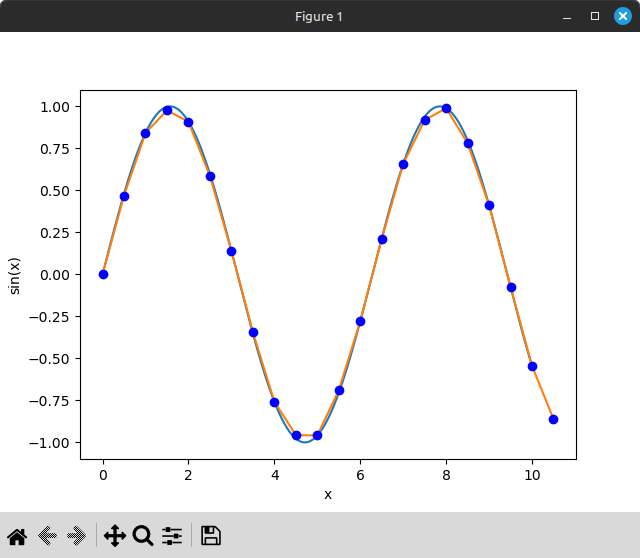
The result:
 2x upsampling via 6-point cubic Hermite interpolation
That’s not a huge difference compared to 4-point cubic Hermite, but it is better!
For one more variant on Hermite interpolation, there’s a formula for 6-point 5th-order Hermite interpolation, i.e. 6-point quintic Hermite interpolation. This usually works a little better than 6-point cubic, though I’m not going to demonstrate it here because the difference is barely noticeable in this toy example of 2x upsampling samples of a sine wave. Even in real examples I often find it hard to notice an audible difference between 6-point cubic Hermite and 6-point quintic Hermite, though there’s definitely an audible difference between 4-point cubic and 6-point cubic.
Now, these Hermite interpolators are not perfect. A perfect resampler (or very close to perfect) will upsample by an integer factor N via zero stuffing, apply a low-pass filter, and then downsample by an integer factor M. However, this can be very computationally expensive, especially if N and M are very large and a steep low-pass transition is desired.
A less perfect but much more efficient solution is to allow the downsampling factor M to be a non-integer, and to apply some sort of interpolation from the upsampled/oversampled signal to the target frequency. This is the main topic of the paper I linked just above, and also essentially the core idea behind windowed sinc interpolation: oversample the source signal by a huge factor (e.g. 512x), apply an extremely high-order FIR low-pass filter, and then linearly interpolate between low-pass filtered samples. The algorithm is complex because it tries to avoid performing any intermediate calculations that are guaranteed not to affect the final result, and also because of how it handles decreasing the low-pass filter’s cutoff frequency when downsampling, but that’s the core idea: oversample, low-pass filter, and interpolate.
However, even this type of resampling can still be somewhat demanding in terms of performance, especially given that we’re talking about a sound chip with 8 different channels that can all play simultaneously at different sample rates. Nevermind something like the PS1 SPU with its 24 channels, or the PS2 SPU with a whopping 48 channels.
Polynomial Hermite interpolation is significantly less compute-intensive, even 6-point quintic interpolation, and in practice it works very well for upsampling without introducing too much audio aliasing. It doesn’t work quite as well for downsampling unless you apply a low-pass filter before interpolating, but for the concrete use case of Sega CD PCM this isn’t a big deal - games very rarely use sample rates higher than the chip’s output sample rate of 32552 Hz. Games need to deal with the chip only having 64 KB of PCM RAM, and additionally, playing at sample rates higher than 32552 Hz will produce noticeable audio aliasing even on actual hardware due to the chip effectively skipping samples.
Supporting Interpolation
In order to apply any form of interpolation to the emulated RF5C164, we’ll need to keep per-channel buffers of recent samples read from PCM RAM instead of only storing the current sample. For 6-point interpolation we’ll need the 6 most recent samples.
We originally had this:
|
|
Let’s replace it with this:
|
|
Here’s the original code for clocking a channel, copied verbatim from the previous post:
|
|
The big change needed is that instead of updating the current sample on every clock, the channel should push a new sample into the buffer every time it advances to a new PCM RAM address. If clocking the channel doesn’t cause it to reach a new PCM RAM address, it should do nothing except update the current address register.
Here’s an attempt at that:
|
|
Now, this isn’t quite a complete implementation. It won’t do the right thing for sample rates higher than 0x0800 / 32552 Hz because it will skip over samples instead of buffering the samples that actual hardware would skip. It’s also skipping the first sample after a channel changes from disabled to enabled. How to handle these cases is left as an exercise for the reader.
The actual interpolation can be applied here, or while mixing the channels. Either way, let’s stick this behind a new sample() method, and let’s make it return f64 instead of u8 so that the interpolation function won’t need to round to the nearest 8-bit integer:
|
|
The actual cubic Hermite interpolation is simply applying the formula up above after converting the 6 most recent samples to f64 PCM and determining what x value to use as the interpolation index.
Fortunately, we already have something we can use for x: the 11 fractional bits of the current address. This fraction represents the channel’s current distance between samples, which makes it perfect to use as the interpolation index x:
|
|
interpolate_cubic_hermite_6p() is just an implementation of the formula from up above.
The mixing/volume code will need to be updated to handle these floating-point samples. I apply the volume multipliers using floating-point math, round to the nearest integer, and then do the remaining mixing calculations using integer math. The exact details of how to do this are also left as an exercise for the reader.
That’s pretty much it, other than supporting other types of interpolation if desired. With this structure it only requires adding a new variant to the PcmInterpolation enum and then adding another match arm to the sample() method.
One thing to note is that 6-point interpolation does introduce an audio delay equal to 3 samples at the source frequency. However, this is well under a millisecond of latency even at the very low sample rate of 10000 Hz, so this is not noticeable in practice.
Time for a comparison!
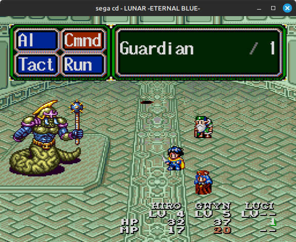
Trying It Out
Yes, it’s the Lunar 2 boss theme again.
Here are four recordings: the original horribly aliased version, the 7973 Hz low-pass filtered version from the last post, an unfiltered version using 6-point cubic Hermite interpolation, and a version that combines 6-point cubic Hermite interpolation with the low-pass filter.
Hmm…the unfiltered cubic-interpolated version does sound a little clearer than the filtered non-interpolated version, maybe? It’s honestly hard to tell a difference. Was this all a waste of time?
High Sample Rate Voice Acting
Let’s try another game. Here’s Popful Mail.
 Why yes, this is a Working Designs localization
During this scene it’s playing its voice acting through the PCM chip with a sample rate of 0x0700. In 5.11 fixed-point decimal, 0x0700 represents 7/8, which given a 32552 Hz base rate is an effective sample rate of about 28483 Hz. That’s pretty high by Sega CD standards!
It’s also playing music using the YM2612 and other PCM chip channels during this scene. I’m going to silence those in order to isolate the voice acting.
Here’s the raw audio with no interpolation or filtering:
That does not sound good, but that was expected.
Here’s with the low-pass filter:
That sounds…a little better, but still very noisy and aliased. Definitely not as radical of an improvement as it was for Lunar 2’s music.
Alright, let’s try cubic interpolation:
That sounds significantly better to me! There’s still noticeable audio noise, but well, 8-bit sample quantization will do that.
For completeness, here’s cubic interpolation combined with the low-pass filter:
Ehh…it cleans up some of the audio noise, but that comes at the cost of making the voice acting less clear. I think I prefer the unfiltered + cubic-interpolated version.
Anyway, as this example shows, there are definitely cases where interpolation produces much better results than simply applying a low-pass filter! Lunar 2 happens to be a particularly good case for the low-pass filter because it usually plays at an exact integer divisor of the PCM chip’s native sample rate.
Not-As-High Sample Rate Voice Acting
I want to revisit one of the comparisons from the previous post: voice acting from Night Trap.
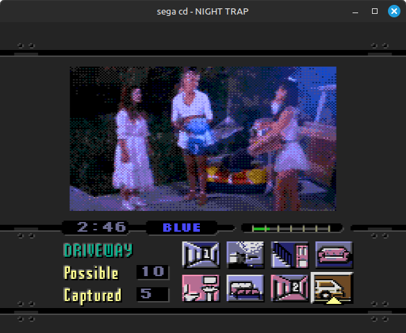
I didn’t mention this in the last post, but Night Trap plays its cutscene audio with a sample rate of 0x04A5, which represents 1189/2048 (effective sample rate ~18899 Hz). This is definitely not an integer divisor of the PCM chip’s native sample rate.
Here are the two recordings from the last post again:
Now here’s a cubic-interpolated version:
This isn’t as drastic a difference as the Popful Mail example, but I do think the cubic-interpolated version sounds noticeably less aliased than the low-pass filtered version.
Here’s the interpolated + filtered version:
I think this one actually sounds the best here. It cleans up more noise than simply interpolating, and unlike the Popful Mail example it doesn’t make the voice acting much less clear. This is kind of expected since the source sample rate is much lower.
Low Sample Rate Music
For one last example, here’s the intro music from Time Gal, another FMV game.

That looks bad in a screenshot, and it looks just as bad in motion where it’s animating at an average of about 6 FPS.
Anyway. This game does some weird things with the PCM chip, but the sample rate here is about 0x0310, which represents 49/128. This is an effective sample rate of ~12461 Hz, quite low.
I’m applying some negative gain in all four of these recordings because this game’s audio is very loud.
The unfiltered + non-interpolated version sounds bad, unsurprisingly, but the other three are interesting to compare. Cubic interpolation removes most of the resampling-induced audio aliasing, and that makes the music sound pretty different.
The unfiltered + interpolated version has some really noticeable audio noise that seems to be caused by clipping - the final mixed PCM chip sample often exceeds the range of signed 16-bit. This happens even without interpolating, but it’s not really noticeable in the non-interpolated version because it blends in with all the other noise and aliasing. The low-pass filter does a decent job at removing most of this noise.
End
In the context of Sega CD PCM, cubic or quintic Hermite interpolation doesn’t always produce a better result than a 7.97 KHz low-pass filter, but when it’s better it can be significantly better.
Like with SNES and PS1, it can change the sound enough in some cases that it’s probably not a reasonable default, but I think it’s a nice optional audio enhancement to support.
Useful References
- Mega CD official documentation: https://segaretro.org/Mega-CD_official_documentation
- Polynomial Interpolators for High-Quality Resampling of Oversampled Audio: https://yehar.com/blog/wp-content/uploads/2009/08/deip.pdf
- The main subject of this paper is interpolating oversampled audio signals, but the Hermite interpolators are noted to work decently well as standalone resamplers in situations where performance is a concern