While the GPU tests I mentioned at the end of my last post are very helpful for validating a lot of GPU rasterization functionality, a new emulator might want the early satisfaction of getting the splash screen’s diamond to render mostly correctly. This post will overview what’s required to make that happen.
Ignore All the Things
To start, you do not need to implement any SPU (Sound Processing Unit) or hardware timers functionality to get the diamond to render. The BIOS will freeze at the main menu if you haven’t implemented some timers functionality, but that’s after it’s already rendered the splash screen.
You can have all unimplemented I/O register reads return 0 and ignore all unimplemented I/O register writes. (Later on you may want to trap on an unimplemented register access so that you know if the BIOS or a game uses some functionality that you haven’t yet implemented.)
In fact, you can even completely ignore interrupts to start with! The BIOS uses the VBlank interrupt for timing synchronization, but it will still render the splash screen even in an emulator that never generates any interrupts, although you’ll see many TTY messages to the effect of VSync: timeout (1:0).
One register you can’t ignore is GPUSTAT, the GPU status register. The BIOS is somewhat sensitive to most of the bits in that register working correctly or it will fail to boot.
DMA
While you can ignore interrupts, you can’t ignore DMA.
The BIOS uses two DMA channels for the splash screen: DMA2 (GPU) and DMA6 (OTC, stands for Ordering Table Clear). OTC DMA is the simpler of the two, but in terms of functionality it makes more sense to discuss GPU DMA first.
Linked List
In general, there are three DMA transfer modes:
- Mode 0: Transfer data all at once
- Mode 1: Transfer data in consecutive blocks of equal size
- In the context of GPU DMA, the GP0 command FIFO can only hold 16 words, so data should be transferred in blocks of at most 16 words to avoid overflowing the FIFO
- Mode 2: Transfer data in blocks, interpreting the data as a linked list
- Only ever used with GPU DMA
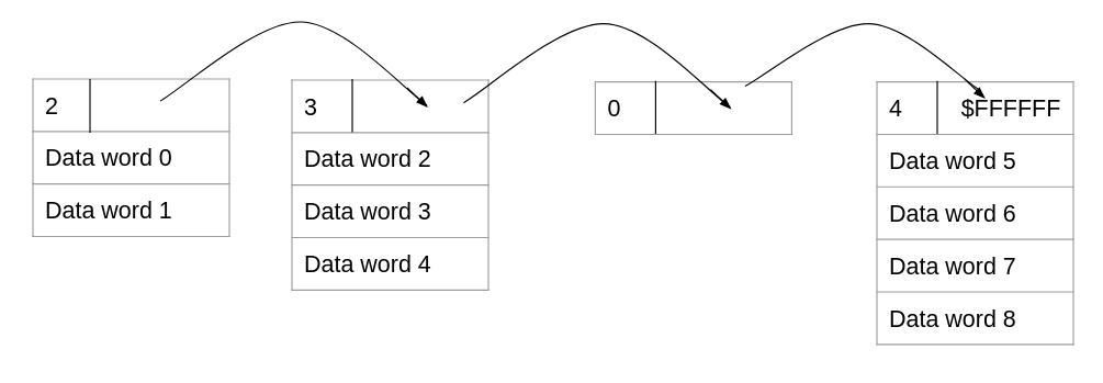
Linked list DMA (mode 2) is the most unusual. Instead of directly sending data from RAM to the GP0 command port, the DMA controller interprets the data in RAM as a linked list where each node can contain a different number of data words.
Each node in the linked list begins with a header word that specifies the number of data words in the node (bits 24-31) and the RAM address of the next node (bits 0-23). The header word is processed without sending it, then the DMA controller sends all of the data words to the GP0 command port, then it moves to the next node. This continues until it encounters a node where the next node address is $FFFFFF, which marks the end of the linked list.
In code, processing linked list DMA might look something like this:
|
|
For getting started you can do the full linked list DMA all at once, but note that some games will modify linked list nodes in RAM after the DMA begins. Some games will even initiate the linked list DMA with an infinite linked list in RAM and then break the infinite loop while the DMA is running! DuckStation’s “Difficult to Emulate Games” page lists games that are tricky to emulate for one reason or another, and a few games are noted specifically for doing infinite linked list DMAs, including some well-known games like Tekken 2 and Syphon Filter.
Ordering Table
Why go through the trouble of making the hardware support this weird linked list DMA? The answer is ordering tables.
The PS1 GPU somewhat infamously does not have a depth buffer (also known as a Z buffer). If multiple polygons overlap, whichever polygon is drawn last will end up “on top”. For 3D graphics, this means that software is responsible for depth ordering: it needs to send polygons to the GPU in depth order from farthest to nearest. Most software accomplishes this using an ordering table in RAM.
Software initializes the ordering table to a linked list full of empty nodes, where the start node represents the highest possible Z value (i.e. the farthest away from the camera). For each polygon in a scene, software computes the average Z value of the polygon’s vertices, and it uses that average Z value to determine where to insert the draw polygon command in the ordering table. The ordering table is laid out in RAM such that it’s not overly difficult to insert data at arbitrary positions. Once the scene is complete, software sends the ordering table to the GPU using linked list DMA, and the GPU will receive the draw commands in depth order from farthest to nearest.
This solution obviously isn’t perfect because it collapses every polygon down to a single Z value rather than taking into account that each vertex could have a different Z coordinate, which can sometimes cause the wrong pixels to show in front. Presumably this was much more cost-effective than giving the GPU a depth buffer.
OTC DMA, or Ordering Table Clear, is built-in hardware functionality to initialize an empty ordering table in RAM. Software gives the DMA controller a starting address and a size and then the DMA controller fills RAM with a linked list of empty nodes, stepping backwards from the start address so that higher Z values correspond to higher addresses in RAM.
psx-spx section on OTC DMA, but this is really quite simple to implement:
|
|
Block
If an emulator is executing DMAs all at once, the only major difference between block DMA (mode 1) and all-at-once DMA (mode 0) is that block DMA needs to compute the total number of words as block_amount * block_size rather than only considering the block size.
As with linked list DMA, some software will not work if block DMA executes all at once and finishes instantly, but a decent amount of software is not bothered by unrealistic DMA timing. Per the DuckStation page, Final Fantasy IX is an example of a game that will not work if block DMA finishes instantly - it will freeze when the game tries to play the opening movie.
First Graphical Output
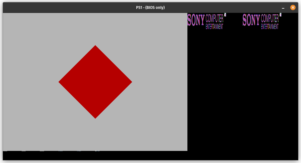
As long as you’ve implemented the CPU-to-VRAM copy command, you should be able to get some graphical output in a VRAM view as soon as you’ve implemented DMA2 and DMA6:
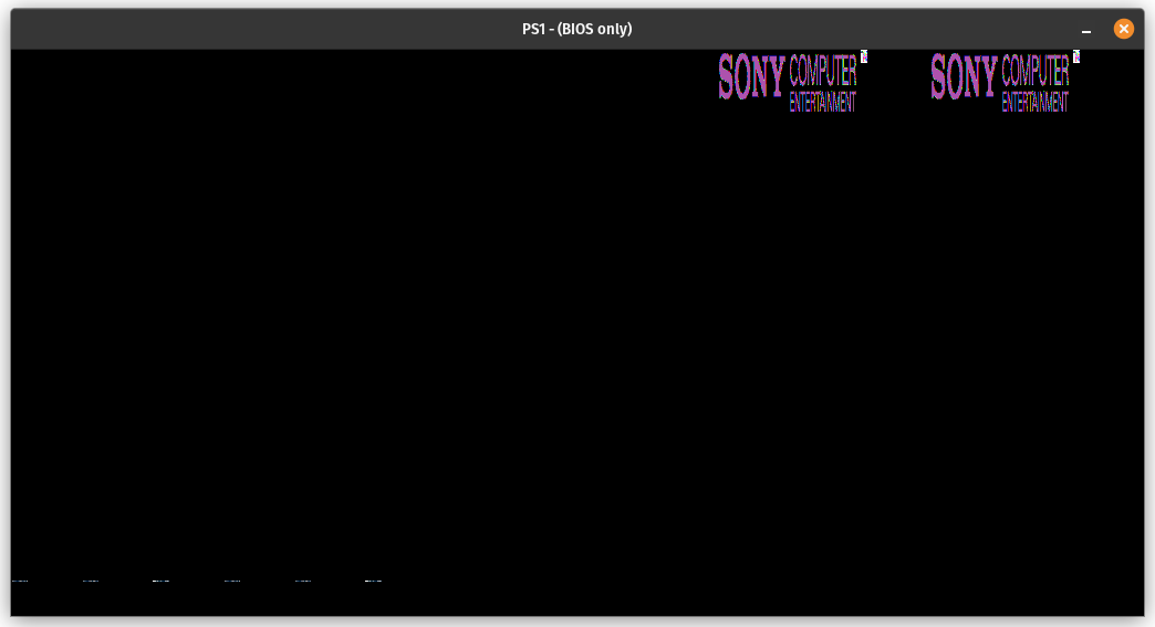
While you need to implement the draw polygon command to get any graphical output inside the 640x480 frame buffer, you can see the Sony Computer Entertainment logo textures to the right (copied twice for some reason), and you can see some CLUTs in the lower-left corner.
Preparing the Scene
The initial batch of GPU commands sent by the BIOS doesn’t make a whole lot of sense, so I’m going to skip ahead to where it changes the resolution to 640x480. Immediately before that, it should configure drawing by sending the following words via linked list DMA:
GP0: $E3000000  // Set drawing area top-left coordinates to (0, 0)
GP0: $E4077E7F  // Set drawing area bottom-right coordinates to (639, 479)
GP0: $E5000000  // Set drawing offset to (0, 0)
GP0: $E100020A  // Texture page configuration, enable dithering
GP0: $E2000000  // Clear texture window settings
GP0: $E6000000  // Clear mask bit settings
Notably, the drawing area is set to the rectangle ranging from (0, 0) to (639, 479), and dithering is enabled for draw commands.
After that it writes some commands to the GP1 command port:
GP1: $05000800  // Set display area top-left coordinates to (0, 2)
GP1: $06C60260  // Set horizontal display range to ($260, $C60)
GP1: $0703FC10  // Set vertical display range to ($10, $FF)
GP1: $08000027  // Display mode: NTSC, 15-bit color, interlacing on, 640x480
These values are pretty standard for a 640x480 frame buffer except for the display area starting at (0, 2) instead of (0, 0) and the vertical display range being 16-255 instead of 16-256. It’s not really clear to me why the BIOS does this.
Next, it sends a draw polygon command via linked list DMA:
GP0: $28000000  // Draw polygon command: 4-vertex, flat shading, untextured, no semi-transparency, color R=0 G=0 B=0
GP0: $00000000  //   1st parameter: 1st vertex coordinates of (0, 0)
GP0: $00000280  //   2nd parameter: 2nd vertex coordinates of (640, 0)
GP0: $01E00000  //   3rd parameter: 3rd vertex coordinates of (0, 480)
GP0: $01E00280  //   4th parameter: 4th vertex coordinates of (640, 480)
This is filling the entire 640x480 draw buffer with the color black.
Now, the PS1 GPU can’t really draw arbitrary 4-vertex polygons. All 4-vertex polygons are rasterized by drawing two triangles: one consisting of the 1st/2nd/3rd vertices, and one consisting of the 2nd/3rd/4th vertices. For an untextured flat-shaded polygon this distinction is insignificant, but it matters when using Gouraud shading or texture mapping because it affects how colors and texture U/V coordinates are interpolated.
To jump ahead a bit, this is the first draw command that isn’t just filling the entire frame buffer with a solid color:
GP0: $380000B2  // Draw polygon command: 4-vertex, Gouraud shading, untextured, no semi-transparency, color R=178 G=0 B=0
GP0: $00F000C0  //   1st parameter: 1st vertex coordinates of (192, 240)
GP0: $00008CB2  //   2nd parameter: 2nd vertex color of R=178 G=140 B=0
GP0: $00700140  //   3rd parameter: 2nd vertex coordinates of (320, 112)
GP0: $00008CB2  //   4th parameter: 3rd vertex color of R=178 G=140 B=0
GP0: $01700140  //   5th parameter: 3rd vertex coordinates of (320, 368)
GP0: $000000B2  //   6th parameter: 4th vertex color of R=178 G=0 B=0
GP0: $00F001C0  //   7th parameter: 4th vertex coordinates of (448, 240)
Phew, that’s a lot of parameters! The draw polygon command has a variable number of parameters depending on the number of vertices (3 or 4), whether Gouraud shading is used, and whether texture mapping is used. There are a minimum of 3 parameters (3-vertex, flat shading, untextured) and a maximum of 11 parameters (4-vertex, Gouraud shading, textured). Even with Gouraud shading, there is no parameter for the 1st vertex color because the 1st vertex uses the color in the command word.
Looking at this specific command, it appears to be drawing a diamond! The left vertex at (192, 240) and the right vertex at (448, 240) are colored red, the top vertex at (320, 112) and the bottom vertex at (320, 368) are colored orange, and Gouraud shading is used to interpolate colors between vertices.
All right, it’s time to start rasterizing triangles.
Triangles All the Way Down
In the PS1 GPU (and most GPUs really), the triangle is the fundamental unit from which 3D scenes are built. The GPU is designed such that it can efficiently rasterize triangles into a frame buffer, and software takes advantage of this by representing each 3D scene as a collection of thousands of triangles. …Well, thousands on the PS1, anyway - modern GPUs can easily handle scenes that are composed of tens of millions of triangles, or possibly even more than that depending on the resolution and effects used.
The PS1 GPU can also render rectangles, but the rectangle edges must be parallel to the X and Y axes, so rectangles are generally only used for 2D graphics such as sprites and HUD elements.
So, how does one programmatically draw a triangle?
Rasterization 101
Broadly speaking, there are two categories of triangle rasterizers: software rasterizers (CPU-based) and hardware rasterizers (GPU-based). While a hardware rasterizer is vastly more performant and enables various graphical enhancements, a hardware rasterizer is also much more difficult to get working correctly in the context of an emulator. You’re not just rasterizing triangles - you want to rasterize triangles in roughly the same way that the PS1 GPU rasterizes triangles. This includes things like semi-transparency and texture mapping with CLUTs, which are both kind of tricky to do in a hardware rasterizer. PS1 is doable at roughly full-speed with an extraordinarily inefficient software rasterizer (ask me how I know) so I’d recommend starting with software.
I am by no means an expert on this topic, so I’ll start by linking some references on how to write your own software rasterizer:
- A Simple, and Trivially Parallelizable Triangle Rasterization Approach
- Optimizing Software Occlusion Culling (mainly posts 6, 7, and 8)
- Developing a Software Renderer
These mention SIMD instructions (e.g. SSE and AVX) as well as GPU acceleration, but I wouldn’t worry about that for a first iteration. Write a really slow rasterizer that works, then you can go back and write a faster one that uses vector instructions or maybe even the GPU.
I’ll make my own attempt to cover the basics, while also highlighting some things that are important to keep in mind for PS1 specifically.
Vertex Ordering
First off, your vertices need to be in a consistent order, either clockwise or counterclockwise. Modern GPUs can use vertex order to cull triangles that are facing away from the camera, but the PS1 GPU does not do this, and in fact it does not care at all how a triangle’s vertices are ordered. A rasterizer does care, so step #1 is ensuring that the vertices are in the desired order.
Let’s say you want the vertices to be ordered counterclockwise. You can first check whether the vertices are already ordered counterclockwise. If they’re not, you can swap the first two vertices and then you’re guaranteed to have a counterclockwise ordering. Well, unless all three vertices are collinear, but that’s its own edge case.
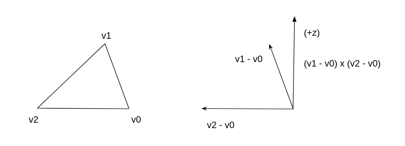
We can check the ordering using the right-hand rule. Let’s say our vertices are V0, V1, and V2 in that order. If the cross product of the vectors (V1 - V0) and (V2 - V0) has a non-negative Z component, that means the vertices are already in counterclockwise order. If the cross product has a negative Z component then they’re in clockwise order, and we can make them counterclockwise by swapping the first two vertices.
Since we only care about the Z component of the cross product, we can skip the full cross product calculation and just do this:
((v2 - v0) x (v1 - v0))z = (v1x - v0x)(v2y - v0y) - (v1y - v0y)(v2x - v0x)
In code:
|
|
Now, in a normal coordinate system as pictured above, this would result in a counterclockwise vertex ordering. However, in the PS1’s vertex coordinate system, the Y axis is inverted: +Y is down and -Y is up. This effectively inverts the sign of the cross product’s Z component, which means that the above function will always produce a clockwise vertex ordering. Which is fine, as long as the code accounts for that (and the inverted Y axis).
A clockwise ordering is actually a good thing if we’re operating in PS1 vertex coordinates. Because of the inverted Y axis, a bunch of calculations in the references that assume the vertices are counterclockwise actually require the vertices to be clockwise in the context of PS1 vertex coordinates.
Bounding Box
Step #2 is to compute a bounding box, a rectangle that should contain every pixel that might possibly be inside the triangle. This is trivial to compute from the vertex coordinates:
|
|
Note that the min/max coordinates are inclusive on both ends.
PS1 has the additional wrinkle of needing to clip pixels outside of the drawing area, but this is easy to implement by restricting the bounding box to be completely inside the drawing area. If this results in an empty bounding box then the triangle is skipped:
|
|
Polygon Fill
And now for the actual rasterization. We iterate over every pixel inside the bounding box, check whether that pixel is inside the triangle, and if it is inside then we color it.
To check whether a given pixel is inside the triangle, we can use the right-hand rule, similar to what we did to determine whether the vertices were in clockwise or counterclockwise order.
Assume V0/V1/V2 are in clockwise order and the Y axis is inverted. For each vertex pair (Va, Vb) in (V0, V1), (V1, V2), (V2, V0): compute the Z component of the cross product (Vb - Va) x (P - Va). If the Z component is non-negative for all three cross products, the pixel is inside the triangle! If any of the three Z components are negative, the pixel is outside the triangle. (The references I linked earlier go into more detail on why this works.)
More concretely:
|
|
For every pixel determined to be inside the triangle, we rasterize it, which for PS1 means writing the 15-bit color value into PS1 VRAM. While the full color value is 24-bit, the PS1 GPU’s draw commands can only output in 15-bit color.
The actual color calculation can be a bit involved, but for the simplest case of flat shading with no texture mapping or semi-transparency, the rasterized color is simply the 24-bit color from the command word truncated to 5-bit color components. This is exactly the same as coloring the pixels from psxtest_cpu.exe’s “draw 1x1 rectangle” commands.
Anyway, that’s the basic skeleton of a software rasterizer! If you wire this up to the emulated PS1 GPU’s draw polygon commands, you ought to see the BIOS render a fade-in from black to light gray using 4-vertex polygons that cover the entire frame buffer:
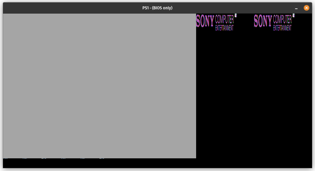
If you handle parsing of draw polygon commands with Gouraud shading enabled, even if you don’t actually implement the Gouraud shading, you ought to get the general shape of a diamond after the fade-in:
However, before touching on Gouraud shading, there’s one more thing to cover.
Top-Left Rule
GPUs generally have algorithms or rules to ensure that if two triangles have a shared edge, pixels that lie exactly on the shared edge will only be rasterized once. The PS1 GPU is no exception. This prevents pixels on shared edges from being double rasterized, which is very important to prevent graphical artifacts when semi-transparency is involved.
Here’s an example of a glitch that occurs in Final Fantasy VII’s intro if you don’t implement this (note the out-of-place vertical line):
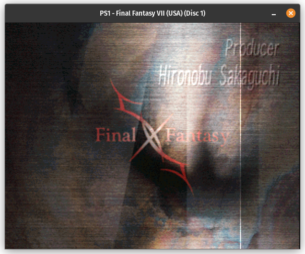
The PS1 GPU uses what is called the top-left rule. If a pixel lies exactly on one of the triangle’s edges, only rasterize it if it’s on a top edge or a left edge. If it’s on a right edge or a bottom edge, skip it. This causes pixels lying on shared edges to only be rasterized once without needing to explicitly check if the edge is shared with another triangle.
To be more precise, all non-horizontal edges are considered to be on the left or right side of the triangle. A horizontal edge is either a top edge or a bottom edge.
This is actually pretty simple to implement using cross product Z components again. If the Z component of the cross product (Vb - Va) x (P - Va) is 0, that means that the point P is collinear with Va and Vb. In other words, it lies exactly on one of the triangle’s edges. If we assume the vertices are ordered clockwise, it only takes a few comparisons to determine the orientation of the edge relative to the triangle.
Let’s extend the is_inside_triangle() function a bit:
|
|
Color Interpolation
We technically have the diamond by now, but it sure would be nice if it was colored correctly!
The diamond’s polygons are rendered using Gouraud shading. Each vertex has its own color, and pixels inside the triangle are colored by interpolating colors between the three vertex colors.
I’m not sure exactly how the PS1’s GPU does this, but in a software rasterizer you can interpolate using normalized Barycentric coordinates. Essentially, you compute a set of three coordinates where each coordinate corresponds to one of the triangle’s vertices, representing roughly how close the given point is to that vertex. For any point inside the triangle, after applying normalization, each Barycentric coordinate is between 0 and 1 and the three Barycentric coordinates sum to 1.
It turns out that you can compute these in terms of the cross product Z components (yes, again). For an edge (V1 - V0) and a point P, the Z component of the cross product (V1 - V0) x (P - V0) is an unnormalized Barycentric coordinate for the third vertex, V2 in this case. To normalize the coordinates, you can divide by the sum, which is guaranteed to equal the Z component of the cross product (V1 - V0) x (V2 - V0). (It also just so happens that this denominator is equal to twice the area of the triangle, which is related to why the math works out.)
If the point is inside the triangle, all three of these cross products are guaranteed to have a non-negative Z component (since that’s exactly what we used for the inside/outside check), so the three coordinates are guaranteed to be between 0 and 1 after normalization.
In code, the calculation might look like this:
|
|
In real code you’d probably reuse the cross_product_z calculations that were previously used for the inside/outside check instead of repeating the calculations twice.
Once we have the normalized Barycentric coordinates, we can use them as weights for the vertex colors:
|
|
And then for final rasterization we truncate the interpolated color from 8-bit components to 5-bit components, just as we did to convert the 24-bit color in the command word to 15-bit for flat shading.
This should be enough to get a kind of correct looking diamond!
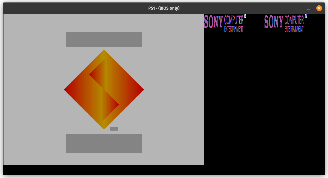
The gray boxes are what (often) happens if you try to render a textured polygon as if it wasn’t textured.
Dithering
The boundaries between different colors are really noticeable in that above screenshot. This is a graphical artifact known as color banding.
In a hardware rasterizer, you could solve this by rasterizing in 24-bit color without truncating to 15-bit, which would make the color transitions significantly more gradual. That’s not as practical to do with a software rasterizer though, and it’s also not accurate to PS1 hardware (though many would argue that it looks better).
Actual hardware solves this using dithering. If dithering is enabled via the appropriate GP0 command, which it is on the splash screen, the hardware will automatically apply dithering to the output of draw polygon commands that use Gouraud shading (or that use texture mapping with color modulation). Dithering reduces color banding by adding a bit of noise to the draw output.
In the PS1 specifically, dithering works by applying a very small offset to each 8-bit RGB color component before truncating to 5-bit components. The offset used is based on the lowest 2 bits of the pixel’s X and Y coordinates.
The dither table, from psx-spx:
  -4  +0  -3  +1
  +2  -2  +3  -1
  -3  +1  -4  +0
  +3  -1  +2  -2
Assuming you have these values in a 2D array of type [[i8; 4]; 4], you can apply dithering like so:
|
|
Implementing dithering makes the color banding much less noticeable:

End
This post is already quite long, so I’m going to end it here. While the splash screen as a whole isn’t complete without texture mapping to make the logos render correctly, the diamond is fully rendered!
As a hint for texture mapping, you can interpolate the texture U and V coordinates between vertices the exact same way that you interpolate the R/G/B color components between vertices for Gouraud shading. This is definitely not how actual hardware does it (and the difference is noticeable in some games), but it will work decently well most of the time.