This is a followup to the previous post on the Sega CD’s PCM sound chip. This post will start by going into more detail on why this chip’s audio output sounds pretty crummy by default, followed by one of two possible solutions that I know of to that problem.
This was originally going to be a single post covering two different approaches to improving Sega CD PCM audio quality, but while writing it I realized that this first approach deserves a more fleshed-out post to itself, if only because it applies to both standalone Genesis and Sega CD. Arguably moreso to Genesis.
The Wrong Way to Upsample Audio
At the end of the last post, I gave an example recording of the boss theme from Lunar 2: Eternal Blue, and I noted that it plays through the PCM chip with a sample rate of 0x0400 / 16276 Hz. This is an exact integer divisor of the PCM chip’s native sample rate of 32552 Hz - why doesn’t this work well in practice, at least in my emulator?
Here it is again, just for convenience (exact same audio file as in the previous post):
I think it’s possible to demonstrate the problem with some graphs.
Here’s a simple plot of a sine wave, just y=sin(x):
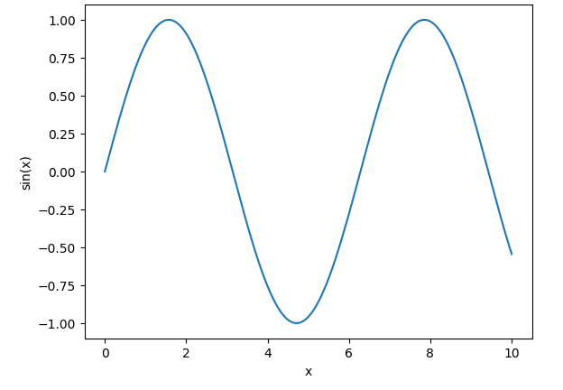 A sine wave
Let’s say we have 11 evenly-spaced samples of this wave, ranging from x=0 to x=10:
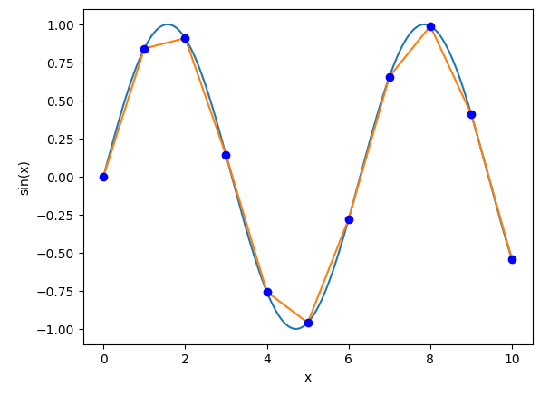 Samples of a sine wave
We’ve obviously lost some detail here, but the samples do track the general shape of the sine wave. A smart audio driver or audio device will be able to mostly figure out what the original wave looked like.
Now let’s upsample to 2x this sample rate by duplicating every sample, as the Sega CD’s PCM chip is doing here. We insert new samples at x=0.5, x=1.5, x=2.5, etc:
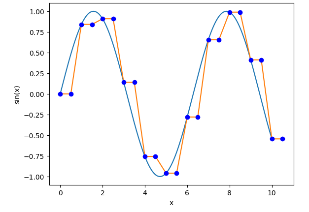 2x upsampling via nearest-neighbor interpolation
That is…not really the same wave! We’ve made it much more rectangular.
This is what causes all of that noise and aliasing. Upsampling this way adds additional information that is not accurate to the original waveform. Also, keep in mind that this is upsampling by an integer factor - the results are much worse when using nearest-neighbor interpolation to upsample by a non-integer factor.
The PCM chip audio output doesn’t sound nearly as bad on actual hardware, so what is actual hardware doing that I’m not?
Low-Pass Filtering
This is a post about Genesis audio. This topic was going to come up at some point!
Disclaimer
I am not even remotely an expert in this field. “This field” being digital signal processing, often abbreviated DSP. This section (this entire post, really) should be taken as an overview of what I’ve researched and what I’ve managed to cobble together in my own experiments, not anything more. I’m largely just writing the high-level overview post that I wish I’d had when I started doing any of this.
I should also note that I don’t fully understand the math that underpins a lot of this, and as such will mostly not discuss it beneath a very high level. It’s possible that some of what I’m doing is kind of nonsensical, or that there are much simpler ways to accomplish the same thing.
That said, I do feel like I eventually stumbled into some interesting results, so I’m going to attempt to describe the path that led to those results. (Also, writing things out helps me recognize errors or holes in my understanding, which happened many times while writing this post.)
Background (Very High Level)
First, it’s important to know that audio signals can be decomposed into component sine and cosine waves of different frequencies. Intuitively, this makes sense - our ears can easily pick out musical notes playing simultaneously at different frequencies.
I’m not going to attempt to go into details on the math involved here, and frankly you don’t need to understand it to take advantage of some of its applications, but I think that having at least a basic understanding is very helpful.
The key concept here is the Fourier transform, though the Fourier series is a little simpler to comprehend as a starting point. Euler’s formula is also helpful background for the Fourier transform.
The phrases “time domain” and “frequency domain” come up very frequently in literature and discussions on these topics. A function being in the time domain means that its input is time, while a function being in the frequency domain means that its input is frequency. In the context of a digital signal, the time domain representation of the signal shows how the signal’s amplitude changes over time, while the frequency domain representation captures the amplitude and phase of the signal’s frequency components.
It’s possible to apply the Fourier transform to a discrete function (e.g. a sampled digital signal) using the discrete Fourier transform (DFT). Implementing the DFT naively is O(N2) which is incredibly slow for large inputs, so in practice the DFT is usually performed using an algorithm called the fast Fourier transform (FFT) which is O(NlogN). However, for best performance, the FFT requires that the number of samples is a power of two.
The important things to know are that audio signals can be decomposed into their frequency components, and that it’s possible to create digital signal filters in the time domain that respond differently to components of different frequencies. The mathematical reasons why this is possible are related to the Fourier transform.
Definition and Practice
A low-pass filter is a signal filter that only passes component waves with low frequencies. In other words, it removes component waves with high frequencies.
There are many different reasons that you might want to apply a low-pass filter to an audio signal or some other signal. For example, in hardware, you might want to remove possible high-frequency noise caused by interference.
An ideal low-pass filter passes all frequencies below its cutoff frequency Fc with zero attenuation, and it fully attenuates all frequencies above Fc. This ideal response is called a brick-wall filter.
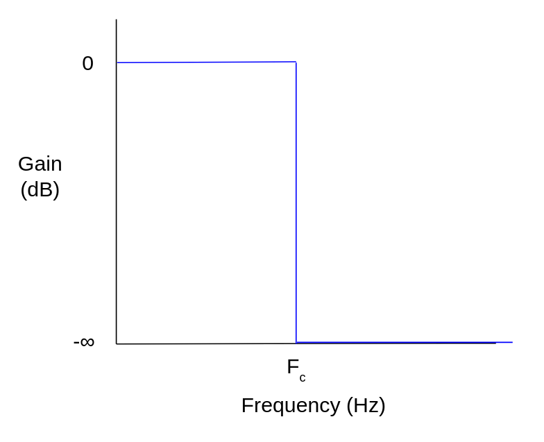 Ideal low-pass filter frequency response
Attenuation is a decrease in amplitude magnitude, which corresponds to a multiplier of less than 1 applied to a digital signal. Attenuation and gain are typically measured in decibels (dB), a unit with a logarithmic scale that is closer to how our ears perceive differences in amplitude/volume. A raw value multiplier of less than 1 corresponds to a negative gain value in dB, or equivalently a positive attenuation value in dB.
The inverse Fourier transform of the ideal low-pass filter response happens to be a multiple of the sinc function. In the context of DSP, sinc is usually defined as:
- sinc(t) = sin(πt) / πt, for t ≠ 0
- sinc(0) = 1
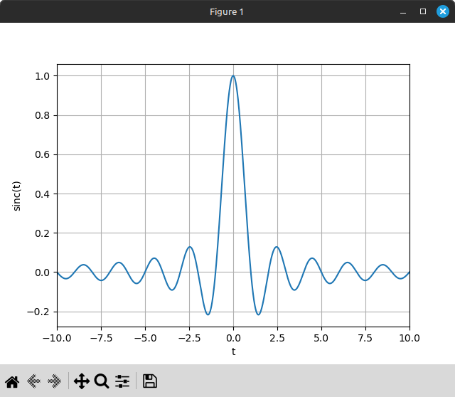 sinc function
Applying sinc in the time domain would produce the perfect frequency response, but applying sinc directly is not possible in reality because it requires an infinite number of input samples in order to capture the input signal’s frequency information with 100% accuracy.
Practical filters in the time domain must approximate the sinc function to produce the desired frequency response. Coefficients of FIR (finite impulse response) filters usually follow the shape of the sinc function, though the actual values are different.
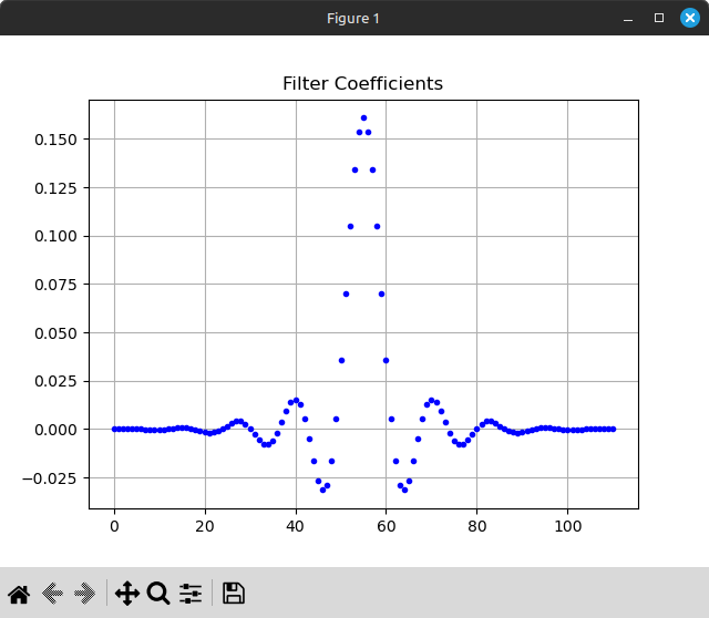 Coefficients of a 111-tap FIR filter generated using a Kaiser window
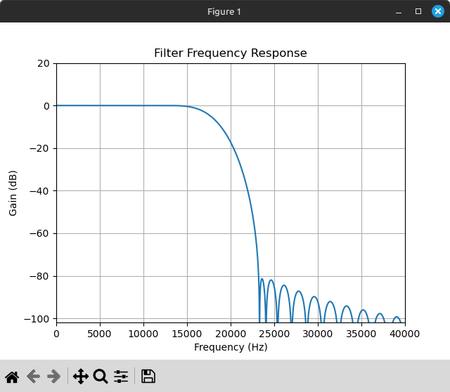 Frequency response of the above FIR filter at source frequency 223721 Hz
Real-time filters must make tradeoffs between a number of performance characteristics, both performance in terms of attenuation behavior as well as performance in terms of computation/hardware requirements. A perfect real-time filter does not exist because a filter that is perfect in terms of quality would be prohibitively expensive to apply in real time.
Before going any further, let’s talk about why low-pass filtering is particularly relevant to Genesis and Sega CD emulation.
In Genesis Hardware
It’s well-known at this point that different Genesis models have very different audio hardware. This thread goes into a lot of the details, but the thing I want to highlight is that the models considered to have the best audio quality have a first-order low-pass filter applied to all audio output with a cutoff frequency of either 3.39 KHz (Model 1 VA0-VA2) or 2.84 KHz (Model 1 VA3-VA6).
There’s some debate as to which is better between the two, but this is largely because the VA0-VA2 models have a preamp issue that can cause audio distortion when outputting audio through the headphone jack, which is required to get stereo audio output from these models. VA3-VA6 fix the preamp issue but have slightly more muffled audio due to the lower low-pass cutoff.
Even a 3.39 KHz cutoff is very low, and this is one of the biggest reasons that audio output from actual hardware often sounds very different from recordings that you find on YouTube and such. Many of these (especially the older ones) were recorded in emulators without a low-pass filter, or with a low-pass filter that has a much higher cutoff frequency. Newer standalone emulators like BlastEm and Ares have a low-pass filter enabled by default.
I should note that there are hardware mods to replace the low-pass filter with one that has a much higher cutoff frequency, like the unfiltered version of the Mega Amp mod, so it’s not like using a high cutoff frequency is objectively worse - some prefer the sharper and clearer sound. It’s just less accurate to original hardware.
In Sega CD Hardware
Sega CD has its own audio output. It can optionally be routed through the Genesis hardware, in which case I believe it would pass through the Genesis low-pass filter, but this is only necessary if you want to output combined Genesis and Sega CD audio through the Genesis headphone jack.
The Sega CD hardware does have its own low-pass filter, of course. Two of them, actually! From schematics in official service manuals, there are two LPF boxes: one applied only to PCM chip output, and one applied later to the mixed PCM/CD-DA output. The latter filter is clearly specified to have a cutoff frequency of 20 KHz, just at the edge of the audible frequency range. This is a reasonable cutoff for filtering CD-quality audio.
The other, more interesting low-pass filter is the one right in front of the PCM chip, and I could not find a single place in the official documentation where this LPF’s cutoff frequency is clearly specified. This is possibly because it might vary between different models.
One service manual has low-level circuit diagrams at the capacitor/resistor level, and I was able to identify where the two PCM low-pass filters are (there’s one for each of the two output channels), but I have exactly zero expertise in making sense of these. From pattern matching to other circuit designs and plugging numbers into formulas, it looks like the PCM LPF cutoff frequency is about 7973 Hz, but I don’t have much confidence in that number.
To show my work, the PCM LPF design looks really similar to the second-order active low-pass design here, just without the gain circuit. It uses the following resistance/capacitance values:
- R1 = R2 = 4700 ohms
- C1 = 2200 pF
- C2 = 8200 pF
pF being Picofarads (1e-12), plugging these numbers in gives about 7973:
|
|
Not sure that’s anywhere near accurate, but given what I know about the hardware, that number seems moderately sensible. So at least for the rest of this post I’m going to assume that it’s in the right ballpark.
How?
Designing a Digital Filter
You could do the math to generate a filter in real time. I don’t know how to do that (at least not yet), so instead I generate the filters offline and hardcode the coefficients in my code. I think that generating a filter in real time probably looks pretty similar in terms of code, only you call your filter generation function during initialization instead of hardcoding the filter coefficients, and you don’t need to do most of what I’m about to describe in this sub-section.
The most common tools for offline digital filter design seem to be the signal package in Octave/Matlab and the signal module in Python’s scipy package. I’m going to use Python because that’s what I’m more familiar with, but Octave and Matlab support the same functionality.
There are a variety of different algorithms for designing different types of filters. The biggest distinction between filters is FIR (finite impulse response) vs. IIR (infinite impulse response). The big difference is implied by their names: a FIR filter’s output depends only on a sliding window of input samples, while an IIR filter’s output depends on both input samples and previous filter outputs.
IIR filters tend to be significantly more efficient, i.e. they require far fewer calculations per output sample compared to a FIR filter with similar attenuation behavior. However, real-time IIR filters can introduce a frequency-dependent phase shift, and higher-order IIR filters can be unstable due to quantization/roundoff error. It’s possible to reduce the risk of instability for higher-order IIR filters by applying them in a form called second-order sections ("sos") rather than the default numerator/denominator form ("ba").
Some functions/algorithms for designing filters:
- firwin / firwin2: Generate a FIR filter using the windowing method (comparable to
fir1/fir2in Octave/Matlab) - remez: Generate a FIR filter using the Parks-McClellan algorithm (aka Remez exchange) (comparable to
firpmin Matlab) - firls: Generate a FIR filter using least squares
- iirfilter: Generate an IIR filter using the algorithm specified by the
ftypeparameter. Supported algorithms are:- Butterworth (
ftype="butter") - Chebyshev Type I (
ftype="cheby1") - Chebyshev Type II (
ftype="cheby2") - Elliptic/Cauer (
ftype="ellip") - Bessel/Thomson (
ftype="bessel") (not recommended for digital filters)
- Butterworth (
I’m sure there are other useful functions as well, but these seem to be the main ones for designing specific types of filters. There are also individual IIR filter design functions like butter, cheby1, etc. as alternatives to the more generic iirfilter.
Alright, let’s make a simple filter! Let’s try to mimic the low-pass filter from the earliest Genesis models, e.g. the Model 1 VA2. It has a cutoff frequency of about 3390 Hz, and it’s known to be a first-order RC filter in hardware, which means that it increases attenuation at 20 dB per decade past the cutoff frequency. A “decade” in this context means a 10x increase in frequency.
20 dB/decade happens to exactly match how a first-order Butterworth IIR filter performs. (That might actually be what it is in hardware; I’m not sure.) So let’s make a first-order Butterworth IIR filter targeting a cutoff frequency of 3390 Hz.
Whatever your choice of tool, it only takes a few lines of code to generate the filter. Here’s an example of how to do it in Python with scipy:
|
|
That script gives me this output:
|
|
Before we do anything with this, it would be nice to visualize the frequency response. This isn’t super important for this simple filter, but it’s very useful when designing more complex filters where you might need to tweak the input parameters a few times. scipy has a freqz function that will compute a digital filter’s frequency response using the fast Fourier transform, and then you can use a package like matplotlib to plot it:
|
|
That gives me this plot:
Looks reasonable enough to me! There’s a very small window of no attenuation, then attenuation gradually increases for the rest of the audible frequency range, and then it increases sharply as frequency approaches the Nyquist frequency. We wanted an attenuation increase rate of 20 dB/decade, which is roughly equal to 6 dB/octave (2x frequency increase), and it does look like it increases at about that rate prior to the sharp drop-off.
A low-pass filter’s cutoff frequency is defined as the frequency at which attenuation is 3 dB, because this is the point at which the filter would remove half of the power in an analog signal. We can zoom in to validate that the cutoff frequency is about 3390 Hz:

It can also be helpful to plot the response with the x-axis on a logarithmic scale, since attenuation in dB is supposed to increase logarithmically relative to frequency in Hz. Adding xscale="log" to the add_subplot() arguments does the trick.
So, this should mostly work? Let’s try it out.
Applying a Digital Filter
IIR filters in numerator/denominator form have two sets of coefficients: the feedforward coefficients b and the feedback coefficients a. The feedforward coefficients apply to input samples and the feedback coefficients apply to previous output samples. (For contrast, FIR filters only have a single set of coefficients, applied to input samples.)
IIR filters are usually designed such that a[0] is 1, so let’s assume that. The generic method for applying an IIR filter is something like this, where x is input samples and y is output samples, both ordered from oldest to newest:
|
|
For our first-order IIR filter, that comes out to just this:
|
|
Let’s throw this into code, for now just hardcoding the filter coefficients as constants:
|
|
We’ll need to integrate two of these, one for YM2612 L output and one for YM2612 R output. This low-pass filter should be applied before resampling because this filter is designed for the YM2612’s native sample rate of ~53267 Hz.
Applying the filter is as simple as sticking a sample = lpf.filter(sample) or equivalent somewhere between the YM2612 output and the resampling code.
Alright, time to see how this sounds!
Finally, An Example
Here’s the first stage theme from Valis, which I picked because I haven’t touched the PSG yet and this song doesn’t use the PSG’s noise channel:
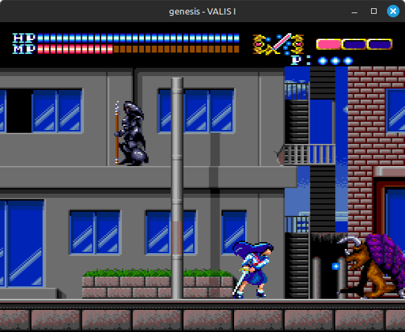
I find that to be a very noticeable difference! Whether it’s better is subjective, but I personally do think this particular song sounds better with the low-pass filter.
Let’s visualize the difference. I’m going to use Audacity to do this.
To avoid including any effects caused by my 53267 -> 48000 Hz audio resampling code, I’m going to write out the raw stream of 53267 Hz YM2612 samples to a file and then import that into Audacity as raw data, specifying that it’s a 53267 Hz audio signal with 2 channels and f32 sample format. (The samples are f64 in my code, but the extra precision is not meaningful at the output stage, so I’m downcasting to f32 before serializing.)
Once the data is imported, Audacity can create a frequency spectrum plot of the audio signal by applying the fast Fourier transform and plotting the result. I’m going to set the x-axis to linear scale to make it easier to see what’s happening at the higher frequencies.
Here’s the unfiltered version:
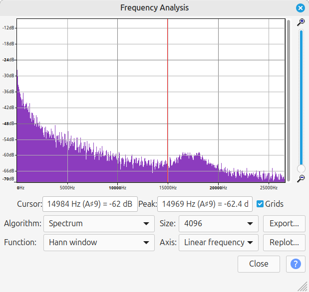
And here’s the 3390 Hz low-pass filtered version, zoomed in a little to try to make the y-axis scale similar:
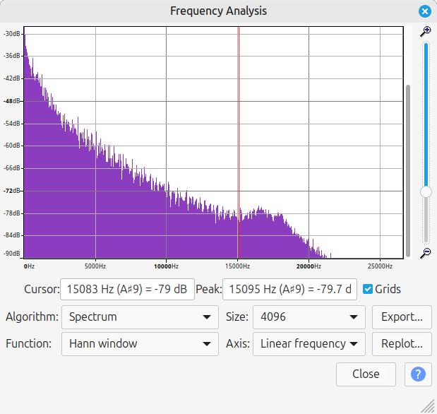
This did seem to have the intended effect! The unfiltered version looks kind of similar in shape as a side effect of the note frequencies that the game is playing, but the filtered version has a noticeably steeper slope. Note that the amplitude measured at 15000 Hz is -62 dB for the unfiltered version and -79 dB for the filtered version. The filter also pretty much completely removed frequencies above roughly 22000 Hz.
More Examples
The same process as above can be applied to generate a low-pass filter for PSG output. It does need to be a separate filter because the PSG outputs at a different sample rate, about 223721 Hz (Genesis mclk / 15 / 16).
A low-pass filter can make a huge difference in games that set the PSG’s noise channel to play at extremely high frequencies. Treasure loved to do this, so here’s the Seven Force boss theme from Gunstar Heroes:
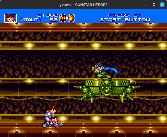
Because this low-pass filter’s cutoff frequency is very low but its attenuation slope is not steep, a lot of higher-frequency audio (i.e. treble) still comes through, but its volume is heavily reduced relative to lower-frequency audio (i.e. bass). This emphasizes the melody in this case. It’s really noticeable in the later sections, 0:45 onwards.
For another Treasure example, here’s Runner AD2025 from Alien Soldier, which plays during the first few stages:
I personally think the unfiltered version of this one sounds really harsh, almost an assault on the ears.
I feel obligated to include a Yuzo Koshiro example, so here’s Go Straight from Streets of Rage 2:
If nothing else, I think this one really benefits from the low-pass filter quieting down the PSG’s noise channel.
Here’s part of the Harley Quinn boss theme from The Adventures of Batman & Robin, which does some wild things with the YM2612 (also a good test of an emulator’s audio resampling code):
One more example, Bad Apple with its 13 KHz PCM audio played through the YM2612’s DAC channel.
I cheated a little in my last post and posted a recording that used a low-pass filter to clean up some of the aliasing, although that low-pass filter wasn’t remotely accurate to the Genesis hardware low-pass filter. The first recording here does not do that. (Although it was recorded with significantly higher-quality audio resampling code than the last post’s recording.)
I think this one is a strong argument for offering an option rather than always applying the 3390 Hz low-pass filter. The 3390 Hz version sounds pretty muffled.
Circling Back: Sega CD PCM
As I mentioned above, Sega CD audio can be routed through the Genesis and its low-pass filter, but ideally it shouldn’t be. In the context of an emulator though, you might want to offer the option! Actual hardware does support this configuration.
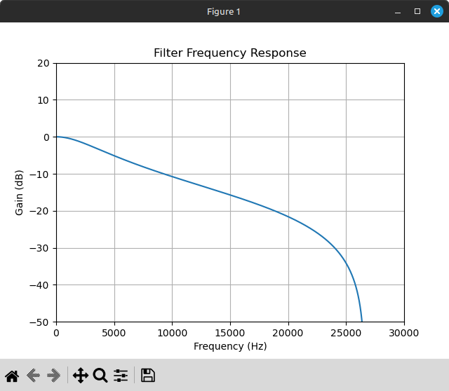
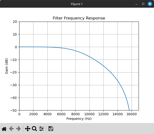
Also as I mentioned above, I think there’s a 7973 Hz low-pass filter in front of the PCM chip, but I don’t have a high level of confidence in that number. We’ll go with it though.
From the circuit diagram, the filter appears to be a second-order active RC filter, which means 40 dB/decade attenuation after the cutoff frequency. We can mimic this in software using a second-order Butterworth IIR filter, which is defined to have exactly this attenuation slope.
The filter generation code is the same as before, only changing the input parameters:
|
|
Here’s the filter frequency response plot, which shows less attenuation at lower frequencies with a steeper slope at the higher frequencies:
Applying a second-order IIR filter is the same as applying a first-order filter except b and a are length 3 instead of 2, so you need the previous 2 input samples and previous 2 output samples instead of only 1 of each. The calculation should be something like this:
|
|
Let’s go back to the example that I ended the last post with, Lunar 2’s boss theme.
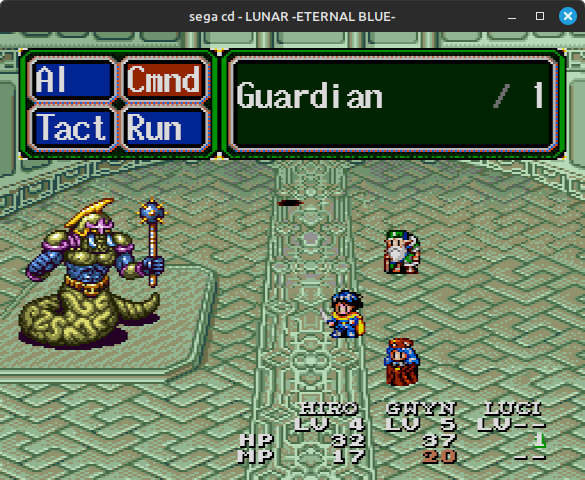
Here’s the original recording again:
Now here’s sticking two 7973 Hz second-order Butterworth IIR filters in front of PCM chip output, one for L output and one for R output:
That sounds much cleaner! It doesn’t grate my ears when I’m wearing headphones anymore. Even if this might not be exactly how actual hardware works, it’s a huge improvement in audio quality. Still nowhere near CD-quality, but not too bad for 8-bit samples at slightly over 16 KHz.
Just for fun, let’s see what happens if we instead use a first-order Butterworth IIR filter with a cutoff frequency of 3390 Hz, mimicing the Genesis low-pass filter:
That definitely softens the highs a lot more. I don’t prefer it to the 8 KHz second-order low-pass filter’s sound, but it’s still a huge improvement over the unfiltered version.
I’d like to highlight that a low-pass filter doesn’t actually fix the horrible aliasing introduced by how the PCM chip resamples its audio channels to 32552 Hz - it just papers over it by identifying most of the added information as high-frequency noise and filtering it out. There are cases where this doesn’t work reliably, though that’s a topic for the next post.
And More Examples: Sega CD (and 32X)
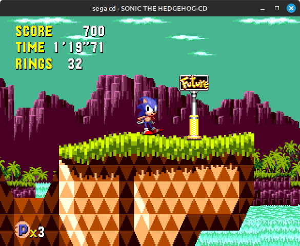
Let’s look at a few more Sega CD PCM examples. First, Sonic CD, which plays all of its past stage music through the PCM chip. This is from the past version of the first zone, Palmtree Panic:
Pretty much every FMV game plays its cutscene audio through the PCM chip. Night Trap is probably the most well known of these, so here’s a bit of voice acting from it:
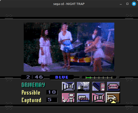
(Yes, Sega CD FMVs almost all look that bad. Even if the resolution was better, color palettes are usually very limited.)
Here’s another example from Lunar 2, but this time voice acting instead of music:

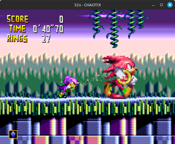
Finally, I haven’t talked about 32X at all, but here’s a 32X example. This is Door Into Summer, the intro stage theme from Knuckles’ Chaotix. In the second recording here I am applying the 3390 Hz filter to the 32X PWM sound chip in addition to the two Genesis sound chips, which mainly serves to quiet down the obnoxious high hat samples in the later parts of the track:
I actually much prefer the low-passed version here. I feel like the volume balance between instruments is all wrong without the filter. The PSG’s noise channel is one of the biggest offenders as usual, but I think even the YM2612 volume sounds off in parts without the filter.
Here’s one more example from the same game that really highlights how much of a difference a low-pass filter can make when the PSG’s noise channel is playing at ultrasonic frequencies:
To Be Continued: Improving at the Source
While a low-pass filter clearly works very well for cleaning up the audio output from the Sega CD PCM sound chip, it is still generating extremely aliased audio at the source due to using nearest-neighbor interpolation to resample from channels’ individual sample rates to 32552 Hz.
The next post will go into detail on a way to improve Sega CD PCM audio quality without needing to apply any audio filters to the chip output, similar to what I described for the SNES APU and PS1 SPU in this post. This is less accurate to actual hardware, but in some cases it can result in significantly improved audio quality compared to just using a low-pass filter. Though there are also other cases where the results are nearly indistinguishable.
Postscript: Subnormal Floating-Point Numbers
When implementing an IIR filter in software, it’s very important to be aware of the existence of subnormal floating-point numbers. It’s possible for an IIR filter to decay to a subnormal number when it should decay to zero, and this can cause extraordinarily poor performance in any downstream filtering or resampling code.
There are a number of ways to have the CPU automatically round subnormals/denormals to zero, but the most efficient ways are all architecture-specific (e.g. the FTZ/DAZ flags on x86), and your options will be further limited by what language and compiler backend you’re using.
This post describes a trick that is not quite as efficient as CPU-level rounding but is architecture-agnostic and branchless: https://www.earlevel.com/main/2019/04/19/floating-point-denormals/
Postscript 2: Audio Resampling
I want to state explicitly that I only used Butterworth IIR filters here because I wanted to emulate how the hardware low-pass filters behave. These are not necessarily always the best choice for a low-pass filter used as part of resampling an audio signal, though they are probably among the simplest to generate in real time if you understand the math or can use a library, and they have a very low performance cost.
I don’t really have a specific recommendation here - there are massive tradeoffs between quality and performance, plus there are many dimensions to “quality”. I personally recently moved to windowed sinc interpolation, which is very high quality, but it can be kind of tricky to implement. There can also be a pretty significant performance impact compared to simpler resampling algorithms, especially for systems with extremely high source frequencies like Game Boy (~2.1 MHz) and NES (~1.79 MHz).
Useful References
- Mega CD official documentation: https://segaretro.org/Mega-CD_official_documentation
- Telling apart good Genesis 1s and Genesis 2s from bad ones: https://www.sega-16forums.com/forum/general-discussion/tech-aid/7756-guide-telling-apart-good-genesis-1s-and-genesis-2s-from-bad-ones
- Low Pass Filter basics: https://analogcircuitdesign.com/low-pass-filters/
- Introduction to Digital Filters: https://web.ece.ucsb.edu/~yoga/courses/DSP/P9_Intro_Digital_Filters.pdf
- FIR Low Pass Filter Design with Remez: https://www.wavewalkerdsp.com/2021/09/22/fir-low-pass-filter-design-with-remez/
- Practical FIR Filter Design: Part 1 - https://www.allaboutcircuits.com/technical-articles/design-of-fir-filters-design-octave-matlab/
- FIR Filter Design: https://www.mathworks.com/help/signal/ug/fir-filter-design.html
- FIR Digital Filter Design: https://ccrma.stanford.edu/~jos/WinFlt/WinFlt_2up.pdf
- IIR Filter Design: https://www.mathworks.com/help/signal/ug/iir-filter-design.html
- Digital Audio Resampling: https://ccrma.stanford.edu/~jos/resample/resample.html