The Famicom allows cartridges to modify the console’s audio signal between the APU (audio processor) and the TV. Most games don’t do anything with this capability, but some games included expansion audio chips on the cartridge board to enable enhanced audio beyond what the console is normally capable of. This post is going to overview a few of those.
I specifically said Famicom because Nintendo removed this capability in US and European NES consoles, so expansion audio was only ever used in Japanese game releases.
Mappers
It doesn’t feel appropriate to talk about expansion audio without first mentioning the topic of mappers.
8-bit consoles like the NES, Game Boy, and Sega Master System all have CPUs with 16-bit address buses. All three of these consoles allocate at least half of the address space to the cartridge, but that is not enough for cartridges where the ROM chip is 64 KB or larger. (Nevermind that many NES cartridges have two ROM chips, one mapped into the CPU address space and one mapped into the 14-bit PPU address space.)
The simplest mappers solve this problem by enabling cartridge ROM banking. As an example, UxROM (mapper 2) is one of the simplest NES mappers: it simply lets games control which 16 KB ROM bank is mapped into the second-to-last 16 KB of the CPU address space. (The last 16 KB is always mapped to the last 16 KB of ROM.) Games can change the selected ROM bank by writing to any address in the last 32 KB of the address space.
There are some more complex mappers that do more interesting things. Many later NES games use the MMC3 mapper, which supports scanline interrupts via a clever/horrible hack that involves watching the PPU address bus to sniff out what the PPU is currently doing. A number of less commonly used mappers support timer interrupts based on counting CPU cycles. On the extreme end is MMC5, which supports…well…I’m not even going to attempt to summarize it. It can do a lot of things that you might not expect the cartridge to do, including expansion audio!
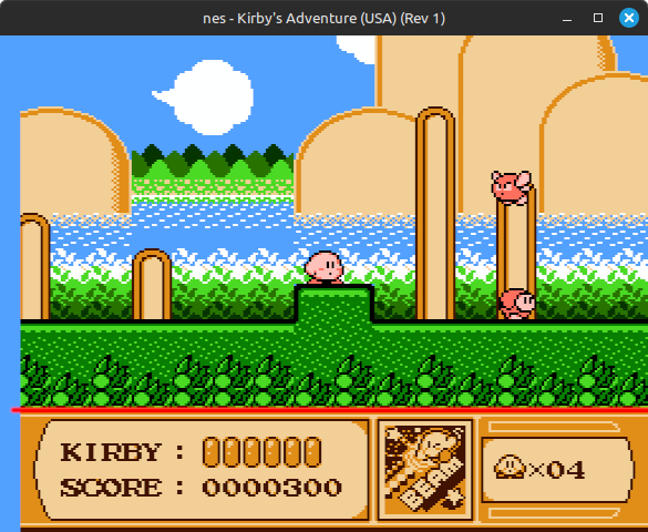 One of many MMC3 games that uses scanline interrupts to split the screen
Bespoke cartridge hardware was very common on the NES/Famicom, especially in Japan. There are literally hundreds of known mappers, and this is one of the most annoying parts of NES emulation because every mapper requires at least a little bit of extra code to support. You don’t really need to emulate that many mappers to cover the majority of the library - you can get quite far by emulating NROM (iNES mapper 0), MMC1 (1), UxROM (2), CNROM (3), MMC3 (4), and AxROM (7). However there’s an incredibly long tail of mappers that were only used in a handful of games, especially once you start looking at unlicensed Asian releases. Even some popular games used bespoke mappers, like Punch-Out!! which is the only MMC2 game.
Granted, not every emulator is going to care about supporting every single mapper - I personally generally don’t unless the game in question looks interesting or seems historically significant in some way. Other emulators do aim to support all known cartridge hardware, or least all known hardware that’s been reverse engineered to the point that it’s possible to emulate.
Some mappers include an audio chip on the cartridge board, which is the subject of this post. The Famicom routes its audio signal through the cartridge before it goes to the console’s A/V out, which allows the cartridge to optionally mix its own audio output with the APU output. This is not possible on the NES because NES consoles don’t pass the audio signal through the cartridge - it goes straight from the APU to the A/V out.
Konami VRC6
Let’s start with probably the most well-known expansion audio mapper: VRC6.
VRC6 was used in 3 games, all by Konami:
- Akumajou Densetsu (aka Castlevania 3 outside of Japan)
- Esper Dream 2
- Mouryou Senki Madara
Castlevania 3 is the reason this mapper is well-known. Its international release uses the MMC5 mapper and features an alternate soundtrack that exclusively uses the NES APU without any expansion audio. The difference is significant.
Here’s a comparison of the song Aquarius, which plays in Stage 6 (on one path):
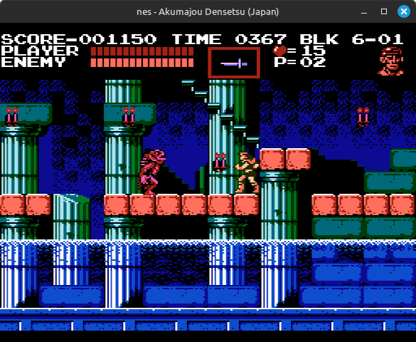
I know which one I prefer!
VRC6 adds 3 additional audio channels for games to use: 2 pulse wave generators and a sawtooth wave generator.
The pulse channels support a 12-bit period, a 4-bit volume, and a 3-bit duty cycle ranging from 1/16 to 8/16. That’s it - these don’t support envelopes or length counters like the APU pulse channels do. The 12-bit period functions as a divider of the NES CPU clock rate: given a period P, every P+1 CPU cycles the channel will advance to the next step in its 16-step duty cycle. The channel output is always either 0 or the 4-bit channel volume.
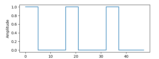 Pulse wave with 6/16 duty cycle
The sawtooth channel supports a 12-bit period and a 6-bit accumulator increment, the latter functioning as the channel volume. Given period P, the channel adds the accumulator increment to an internal 8-bit counter every 2*(P+1) CPU cycles, until the 7th such step where it resets the counter to 0. The highest 5 bits of this internal 8-bit counter are used as the channel output.
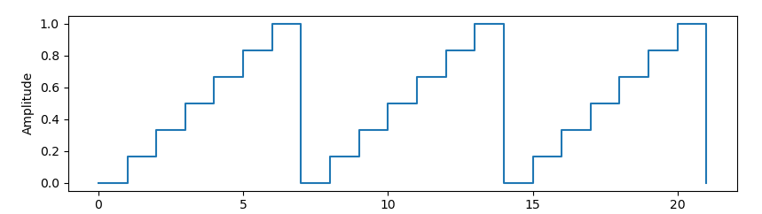 Sawtooth wave with VRC6-style steps
It is possible for the 8-bit counter to overflow if the accumulator increment is set too high. An increment value of 43 or higher will cause the counter to overflow before it resets to 0 at the 7th step, which does not produce a very nice sound. An accumulator increment of 42 should be considered maximum volume from software’s perspective.
Here are a few recordings demonstrating which parts of the above song come from which parts of the hardware. The first recording is the NES APU output, the second recording is all 3 VRC6 channels mixed together, the third is the 2 VRC6 pulse channels, and the last is the VRC6 sawtooth channel:
The audio hardware is really pretty simple, but Konami used it well. The sawtooth channel in particular gives VRC6 music a pretty unique sound compared to other NES music, though it is quite loud.
Sunsoft 5B
Next up is Sunsoft 5B, which was used only in the Japanese version of Gimmick. Variants of this mapper were used in other games, such as Batman: Return of the Joker, but none of these variants include expansion audio.
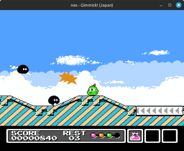
The expansion audio chip is a YM2149F, a Yamaha-licensed variant of the AY-3-8910. This is a pretty simple PSG sound chip with 3 square wave generators, a noise generator, and an envelope generator. It’s kind of similar to the SN76489 sound chip in the Sega Master System and Game Gear, though not exactly the same.
Gimmick doesn’t use any of the noise or envelope functionality, so I’m not going to say too much about those. It’s maybe worth noting that there are only 3 audio channels, 1 for each square wave generator, and that the noise and envelope generators are shared across all 3 channels. It’s possible to individually configure whether each channel outputs noise and/or uses the envelope generator for volume.
Each of the 3 square wave generators is configured using a 12-bit period and a 4-bit volume. Given period P, every 16*P CPU cycles, the wave generator’s output flips between 0 and maximum amplitude (determined by volume). A period of 0 is treated as if it was 1.
This audio chip has a logarithmic DAC, unlike whatever the APU’s DAC is doing. The YM2149F DAC supports 5-bit sample resolution where a change of 1 corresponds to a volume change of 1.5 dB (decibels).
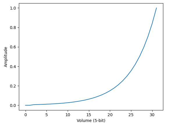 YM2149F theoretical volume curve
Channel volumes are 4-bit - the lowest sample bit can only be set by the envelope generator. Hence, a change of 1 in the 4-bit channel volume corresponds to a volume change of 3 dB.
The DAC is easy to emulate using a 16-entry lookup table. A volume change of N dB is equal to a multiplier of 10^(N/20), so you can build the table like so:
|
|
…Well, that almost works. Hardware tests have shown that channels playing at maximum volume seem to be much quieter than they should be relative to the second-highest volume, and this is exacerbated when multiple channels are playing at very high volumes. This doesn’t really affect Gimmick though.
Here’s the above song, split into the parts from the APU channels and the parts from the YM2149F channels:
The additional channels don’t radically change the sound, but they do enable additional harmonic notes.
If you’re wondering where that bass instrument is coming from, that’s being played through the APU’s DMC (delta modulation channel). It’s surprisingly not anything related to expansion audio!
Nintendo MMC5
MMC5 has the kitchen sink. Of course it has expansion audio too!
This mapper wasn’t used by too many games, probably because it was expensive. The most well-known MMC5 game is easily the international release of Castlevania 3, which does not use MMC5 expansion audio. To be more precise, it couldn’t use expansion audio because US and European consoles don’t support it.
MMC5 includes 3 additional audio channels: 2 pulse wave generators and an 8-bit PCM channel. Only one game is known to use the PCM channel, a mahjong game called Shin 4 Nin Uchi Mahjong. A few Japanese releases use the additional pulse channels, but most MMC5 games don’t use the expansion audio much if at all.
This mapper being designed by Nintendo, the pulse wave generators work almost exactly the same way as the APU’s 2 pulse wave generators. There are a few differences: the most notable are that there’s no frequency sweep functionality, and that MMC5 has its own frame counter that is not configurable. (The frame counter controls the envelope and length counter update rates, as well as frequency sweep update rate in the APU channels.)
The PCM channel plays unsigned 8-bit PCM samples. Software can write PCM samples directly to a register, or there’s a “read mode” that seems to automatically start playing any value that the CPU reads from the address range $8000-$BFFF. Shin 4 Nin Uchi Mahjong appears to only use the “write mode” where it writes samples directly to the register. The channel can’t play 0 as 0 is a special value used to trigger an interrupt, so the sample range is +1 to +255.
There’s not really much else to say here! The MMC5 pulse channels are just APU pulse channels minus some features, and the PCM channel is really simple. While MMC5 in general is probably the most complex mapper to emulate, its expansion audio is pretty straightforward.
Here’s the intro song from Just Breed, an RPG that uses the additional pulse channels as part of its music:
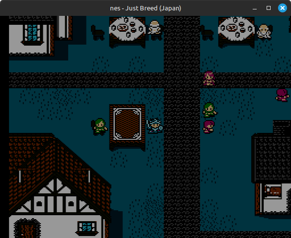
(That screenshot is so dark because the game sets all three PPU color emphasis bits, which darkens all colors. Though my emulator’s current palette is probably darkening the colors too much when games do this.)
The popping noises in the MMC5-only recording are from the game adjusting volumes of channels while they’re outputting a constant amplitude (or oscillating more rapidly than is audible).
The aforementioned mahjong game uses the PCM channel for sound effects and voice samples. Here’s an example of the tile sound effect that it plays constantly:
And here’s an example voice sample:
Namco 163
Now for a more obscure example: Namco 163.
This board shares an iNES mapper number with the Namco 129 board, which is very similar, but none of the Namco 129 games ever used expansion audio.
There are 10 games that use Namco 163’s expansion audio functionality. The most well-known is easily Megami Tensei II, developed by Atlus and published by Namco.
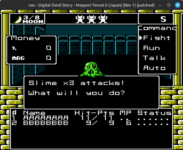
This game got remade for the Super Famicom, but some people prefer the original Famicom version specifically because of its soundtrack.
The Namco 163 expansion audio is a wavetable chip that plays 4-bit PCM samples from 128 bytes of internal wavetable RAM. It supports up to 8 different channels playing simultaneously, though using more than 6 channels can cause an audible high-pitched ringing noise on some consoles.
The PCM samples are unsigned 4-bit, but before applying volume the chip applies a bias of -8 in order to convert to signed. Volume is 4-bit, so this results in channel outputs ranging from -120 to +105.
Each active channel uses 8 bytes at the end of wavetable RAM to store internal configuration (frequency, base address, loop length, volume) and internal state (phase), so it’s not possible to use the full 128 bytes of RAM for samples. With all 8 channels active you’re limited to 64 bytes of RAM for samples, though you can use more RAM for samples if fewer channels are active.
Megami Tensei II uses 4 channels. There are two games that use all 8 channels: King of Kings, and Erika to Satoru no Yume Bouken.
Here’s the Battlefield song from above, splitting out the APU output from the N163 output:
In this song at least, it uses the APU triangle and noise channels for percussion while it uses the Namco 163 wavetable channels for everything else.
The audio hardware does not mix channels. Instead, it multiplexes them through its DAC, so at any given point in time it’s only actually outputting audio from 1 channel. It cycles through active channels at a rate of one step per 15 NES CPU cycles.
This multiplexing is what causes audible ringing when using 7 or 8 channels. When playing 6 or fewer channels, the chip cycles through channels quickly enough that any audio artifacts caused by the multiplexing are not audible. When playing more than 6 channels, this is not the case - there are audible audio artifacts.
Here’s an example from King of Kings using all 8 channels (warning, this is very unpleasant):
The NTSC NES clock rate is defined as 236.25 MHz / 11 / 12, roughly 1.79 MHz. The chip steps through channels at a rate of 1 channel per 15 CPU cycles, so when all 8 channels are active it steps through full 8-channel cycles at a rate of ~1.79 MHz / 15 / 8, which is about 14915 Hz. This is within the audible frequency range, and that is a problem!
The chip designers probably expected the audio output to be filtered by a low-pass filter with a fairly low cutoff frequency. Here’s the result of applying a 4th-order Butterworth low-pass filter with a cutoff frequency of about 7000 Hz:
That sounds much better! Unfortunately, low-pass filtering hardware varies by console, so even on actual hardware this game can sound terrible depending on the setup.
Most emulators avoid this problem by mixing all active channels instead of multiplexing them. The mixing calculation is simply the sum of all active channel outputs divided by the number of active channels. This produces a much nicer sound without needing to apply a filter:
The last thing to note with this mapper is that different cartridges seem to apply significantly different levels of amplification to the expansion audio output. This was investigated and is documented in this thread: https://forums.nesdev.org/viewtopic.php?t=16910
Konami VRC7
Finally, Konami’s other expansion audio mapper: VRC7.
This mapper was used in two games, but only one of them uses the expansion audio chip: Lagrange Point.
Where all of the previously-described mappers include various PSG wave generators and/or PCM playback channels, VRC7 sticks a Yamaha FM synthesis sound chip on the cartridge board. This makes it significantly more complex to emulate than the other mappers. Yamaha FM chips tend to be not well-documented as far as how they actually work, and all of the feedback and modulation means that mistakes can be extremely painful to debug.
But first, an example:
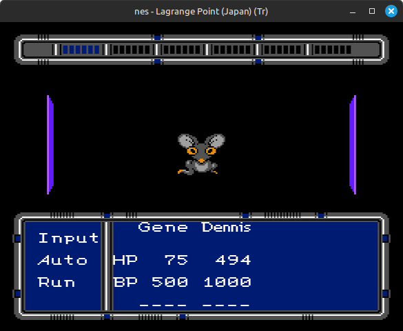
Definitely not a typical NES sound! That’s all from expansion audio - Lagrange Point only really uses the APU for sound effects.
The VRC7 audio chip is a customized version of the Yamaha OPLL (aka YM2413), which is itself a cost-reduced version of the OPL2 (aka YM3812). OPL2 and its successor OPL3 were included in many popular PC sound cards in the late 80s and 90s (e.g. SoundBlaster), while OPLL was most notably used in the Sega Master System’s FM sound expansion and some MSX sound cartridges.
There are three major differences between VRC7 and OPLL:
- VRC7 does not support the rhythm/percussion instrument mode
- VRC7 only has 6 usable channels instead of 9
- It technically does have 9 channels, but the last 3 are only usable in a debug mode that is not normally accessible
- VRC7’s instrument patch ROM is completely different from OPLL’s
These OPL chips are technically related to the YM2612 chip (aka OPN2) used in the Sega Genesis in that they’re all FM synthesis chips designed by Yamaha, but the OPL chips (L-family) work quite differently from the YM2612 (N-family). The YM2612 is much more closely related to the YM2608 chip (aka OPNA) used in the NEC PC-8801 and PC-9801.
VRC7/OPLL is fairly simple as far as FM chips go, at least in concept. The details of how exactly it works are…hairy. I’m going to attempt to offer a high-level overview of its functionality.
Each of the 6 channels contains 2 sine wave generators, called operators. One operator is the carrier and the other is the modulator. The modulator’s wave output is not directly audible - instead, the modulator’s wave output is used to dynamically adjust the carrier wave generator’s phase, and then the carrier’s wave output is what’s used as the channel output.
This dynamic phase adjustment is called phase modulation. You could also call it frequency modulation as it’s effectively constantly altering the sine wave’s frequency, but the way it’s implemented in the chip is more of a phase adjustment than a frequency adjustment.
 Two of many possible examples of phase modulated sine waves
The modulator also supports self-feedback, where the modulator can phase modulate itself using the average of its last two operator outputs.
The modulator and carrier must use the same base frequency for their sine wave generators, but they can individually configure a frequency multiplier ranging from 0.5x to 15x the base frequency.
To try and make this a little more concrete, if you ignore most of the chip’s functionality, at a very high level clocking a channel works kind of like this:
|
|
Of course, actual hardware uses lookup tables instead of actually computing sines in real time. Actual hardware is also not doing anything in floating-point - it’s all fixed-point math, with bit shifts all over the place to convert between different scales. There’s a lot that’s missing or inaccurate in this heavily simplified example snippet, but hopefully it somewhat demonstrates how the chip performs phase modulation.
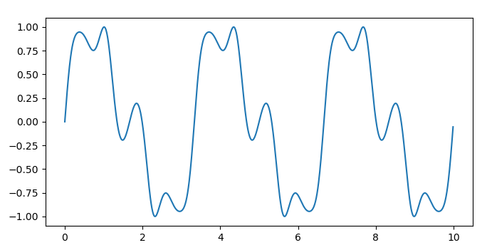
This technique of using one sine wave generator to phase modulate another sine wave generator enables the chip to produce a large variety of different sounds. For a very simple toy example, here’s a 400 Hz sine wave:
Here’s that same 400 Hz sine wave but phase modulated using a 1200 Hz sine wave, with a constant amplitude multiplier applied to the modulator’s output:
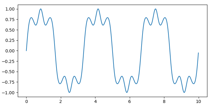
And here’s phase modulating using a 2000 Hz sine wave:
This becomes even more powerful when combined with ADSR envelopes, which can be configured individually for each operator. Envelopes are normally associated with volume, but when used with the modulator they can automatically adjust the level of phase modulation over time.
The chip also supports some additional functionality like key scaling (scale envelope change rate based on frequency), vibrato (frequency oscillation), tremolo (volume/amplitude oscillation), and wave rectification (zero out the negative half of the sine wave).
Now, one way that OPLL reduced costs relative to OPL2 was by eliminating the ability to use a custom instrument patch for each channel. The instrument patch is what specifies almost all channel and operator configuration. OPLL supplies a fixed set of 15 instrument patches that software can select from, with support for only one custom instrument patch at a time.
When using a fixed instrument, software can only configure the channel’s base frequency, a constant overall volume level applied to final channel output, and a “channel sustain” bit that affects some ADSR envelope behavior related to key off. Everything else is part of the instrument patch: ADSR envelope settings, key scaling settings, whether vibrato and/or tremolo are enabled for each operator, per-operator frequency multipliers, etc.
VRC7 is the same as OPLL in this regard, although the fixed set of 15 instrument patches is completely different between the two chips.
That’s mostly it for a high-level overview, although actually emulating the thing is quite difficult to get right. If you’re interested in writing your own implementation, I’d recommend looking over OPLL/YM2413 and OPL2 resources in addition to VRC7 resources, because there’s far more documentation available on OPLL and OPL2 than there is on VRC7. A few maybe helpful starting points:
- YM2413 application manual: https://www.smspower.org/maxim/Documents/YM2413ApplicationManual
- YM2413 reverse engineering by andete: https://github.com/andete/ym2413
- VRC7 notes by Disch: https://forums.nesdev.org/viewtopic.php?f=3&t=9102
- There are some inaccuracies here, but might be helpful as a secondary perspective on how the chip works
Others
The NESDev Wiki has a full list of (known) games with expansion audio: https://www.nesdev.org/wiki/List_of_games_with_expansion_audio
The biggest list there is under the Famicom Disk System, which adds an additional audio channel. That’s a full-fledged console add-on though, not just a mapper.
The rest are not games/software that I’ve ever heard of before. Most seem to use the expansion audio only for speech synthesis or other voice samples.