Rather than covering a single game, this is a topic post that covers six different bugs in my implementation of the Game Boy Color’s HDMA feature (HBlank direct memory access). Not every GBC game uses this feature, but a decent number do, and a few games will break pretty badly if it’s not emulated fairly accurately (moreso in terms of behavior than timing).
HDMA Overview
One of Game Boy Color’s new hardware features over the original Game Boy is VRAM DMA, which copies data from ROM/RAM to VRAM at a much higher rate than is possible using software. It copies 2 bytes per CPU M-cycle in normal speed mode (~4 MHz CPU clock speed) and 1 byte per M-cycle in double speed mode (~8 MHz).
For comparison, it’s impossible to copy more than 1 byte per 5 M-cycles in software, and that’s assuming an unrolled loop which you might not want to do for code size reasons. 8 or 9 M-cycles per byte is more realistic without loop unrolling.
VRAM DMA has two modes:
- General-Purpose DMA (GPDMA / GDMA): Copies all at once
- HBlank DMA (HDMA): Copies in chunks, 16 bytes per scanline during active display
Unlike the Game Boy’s OAM DMA feature, VRAM DMA halts the CPU while it’s actively copying bytes. GPDMA halts the CPU until the entire transfer completes. HDMA halts the CPU while it’s transferring a 16-byte chunk, but between chunks the CPU executes normally.
When HDMA is active it performs a 16-byte transfer at the beginning of each line’s horizontal blanking period (hence “HBlank DMA”), right after the PPU finishes rendering the line to the display (see PPU modes diagram). This is useful for performing transfers during active display, since both manual CPU writes and GPDMA will have their VRAM writes discarded by the PPU if they write while the PPU is fetching data for rendering (PPU mode 3).
VRAM DMA is configured and initiated using 5 registers:
- HDMA1 ($FF51): Source address, high byte
- HDMA2 ($FF52): Source address, low byte
- HDMA3 ($FF53): Destination address, high byte
- HDMA4 ($FF54): Destination address, low byte
- HDMA5 ($FF55): Mode (bit 7), length (bits 0-6), and initiate DMA (any write)
Both the source and destination addresses are forcibly aligned to a 16-byte boundary. The hardware ignores the lowest 4 bits written to HDMA2 and HDMA4.
The destination address (HDMA3-4) is always in the VRAM address range of $8000-$9FFF. The hardware (mostly) ignores the highest 3 bits written to HDMA3 and forces the address to this range.
The source address can be any 16-bit address, but VRAM DMA will only work properly when reading from cartridge ROM/RAM ($0000-$7FFF / $A000-$BFFF) or GBC working RAM ($C000-$DFFF). Other source addresses cause VRAM DMA to read undefined values.
Writing to HDMA5 initiates VRAM DMA in addition to setting the length and mode. The highest bit controls whether the DMA mode is GPDMA (0) or HDMA (1).
The lowest 7 bits in HDMA5 specify the transfer length, as a multiple of 16 bytes minus one. DMA decrements the 7-bit length every 16 bytes, and the transfer ends when the decrement overflows from 0x00 to 0x7F. Therefore the total transfer length in bytes is 16 * ((HDMA5 & 0x7F) + 1), ranging from 0x10 / 16 bytes (length 0x00) to 0x800 / 2048 bytes (length 0x7F).
HDMA5 is both writable and readable. On reads, the highest bit indicates whether an HDMA is currently in progress (0 meaning yes in progress), and the lowest 7 bits contain the current 7-bit length. When an HDMA is running, software can see the length decrement after each 16-byte chunk transfer.
Alright, now on to the more interesting part.
Game Boy Assembly
Before pasting a bunch of assembly snippets, a very small bit of info on the Game Boy CPU: its assembly syntax and instruction names are extremely similar to those of the Z80, but the GB CPU is not an actual Z80 - e.g. it’s missing the index registers, the second register file, the separate I/O address space, and the block transfer instructions such as LDIR. It also has fewer processor status flags, some instructions behave a little differently (e.g. DAA), instruction timings are quite different…it’s a different CPU.
In terms of functionality, the GB CPU is really closer to 8080 than Z80 despite using Z80’s assembly syntax, though it does have the Z80’s $CB-prefixed instructions (single-bit instructions and shift/rotate/swap on registers other than A).
Register overview: https://gbdev.io/pandocs/CPU_Registers_and_Flags.html
Instruction reference: https://rgbds.gbdev.io/docs/v0.9.4/gbz80.7
Pokemon Crystal Version
When HDMA is active, it’s possible for software to prematurely terminate the HDMA by writing to HDMA5 with the highest bit clear. Missing this is a pretty well-known pitfall in HDMA emulation because a very popular game depends on emulating it correctly: Pokemon Crystal Version.
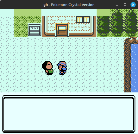
 One way that bad HDMA emulation can break Pokemon Crystal
Here’s a full disassembly of the routine that it uses to perform an HDMA here (yes, it’s long, I wanted to put the whole thing here before breaking it into pieces):
|
|
There’s a lot going on here, and clearly the res 7, [hl] instruction at the end is what can create havoc in an emulator that doesn’t properly emulate HDMA cancellation, but let’s analyze this to see what the game is trying to do.
First, the address setup:
|
|
This part is straightforward - it just takes the addresses passed in via the D/E/H/L registers and writes them to the GBC HDMA registers. The ANDs are not actually necessary because the hardware just ignores the bits that the game masks out here, but whatever, doesn’t hurt anything.
The ld b, $7f instruction is setup for the next part of the code. Not sure why it’s at the beginning of this section rather than the end, but it’s fine since it doesn’t use the B register for anything else here.
Next is this wait loop:
|
|
All together, this snippet waits until the current scanline is less than (127 - (length - 1)), presumably to ensure that HDMA will finish by line 128 in the current frame.
This is not necessary from a hardware perspective. HDMA pauses during VBlank (lines 144-153), but an incomplete HDMA will resume after the first line of the next frame. Getting ahead a bit, but I think the game only does this because of some line counting logic later in this routine that would break if the HDMA pauses in the middle of it.
After this is two wait loops before it starts the HDMA:
|
|
It first waits until the lowest two bits of the STAT register read 0, meaning that the PPU is in mode 0 (HBlank). Once it sees a 0 it then waits until the lowest two STAT bits are not 0, indicating that the PPU has reached the next line and entered mode 2 (OAM sprite scan). This is a very common pattern for timing writes at a specific point in the scanline.
It then finally initiates the HDMA by writing to HDMA5. The first 16-byte chunk will copy at the beginning of the current line’s HBlank period.
The game keeps interrupts disabled during this and the next part of the code in order to ensure that the polling/counting it’s doing here don’t get thrown off by any interrupts.
The final part of the routine:
|
|
This is very curious.
It seems to be waiting for the HDMA to finish, but instead of polling the HDMA5 register, it’s counting scanlines by polling the LY register and decrementing C every time LY changes. When C decrements to 0, it clears HDMA5 bit 7, then it re-enables interrupts and returns.
The thing is, as I mentioned up above, HDMA doesn’t terminate when the length decrements to 0 - it terminates when the decrement overflows from 0 to 0x7F. So, when the game executes that res 7, [hl] instruction, the HDMA still has one 16-byte chunk left to copy.
The RES instruction doesn’t actually do a single-bit write. It can’t, that’s not how the hardware works. It reads the existing 8-bit value, clears the specified bit, then writes back the modified 8-bit value. This can cause some surprising behaviors when using it on memory-mapped I/O registers, though in this case all that really matters is that it writes to HDMA5 with bit 7 clear while an HDMA is active.
Normally, when no HDMA is in progress, writing to HDMA5 with bit 7 clear will initiate a GPDMA with length specified in the lowest 7 bits. If an HDMA is in progress however, the write instead terminates the HDMA and does not start a GPDMA.
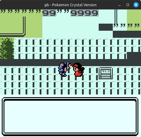
In this particular case, an HDMA is in progress with length at 0, so the game terminates it on the line where it’s set to copy its last chunk. The game actually depends on not copying that last chunk or there will be graphical bugs:
 Glitched row of 16 tiles in the top-left corner
I’m not sure if the programmers didn’t completely understand how HDMA works or if this was a workaround to account for the length in HDMA5 being a -1 value rather than the actual length. Though in the latter case, I don’t know why they wouldn’t have just decremented the length by 1 before writing it to HDMA5…
Pokemon Gold and Silver don’t use VRAM DMA at all as far as I know, so this is code that was written specifically for Crystal.
Anyway, the fix for this is simple: if an HDMA is in progress, writing to HDMA5 with bit 7 clear should terminate the HDMA and should not start a GPDMA.
Toki Tori
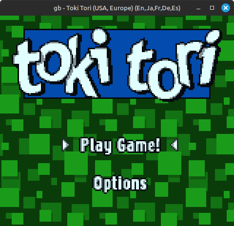
This is supposed to be Toki Tori’s title screen:
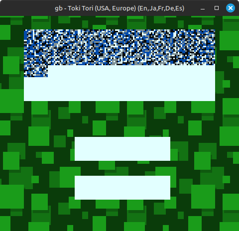 Toki Tori
This was caused by a major oversight in emulating HDMA5 reads that I’m honestly surprised didn’t break more games than it did.
The first thing I noticed that seemed odd is that it sometimes changed the MBC5 cartridge ROM bank mid-HDMA while the HDMA source address was set to e.g. $5800 or $6000, right in the middle of the mappable 16 KB ROM bank.
This didn’t make much sense, so I looked at what it did between the HDMA5 and ROM bank writes (they aren’t far apart) and found this loop:
|
|
HDMA5 bit 7 is supposed to read 0 if an HDMA is in progress and 1 if not. This seems like a very reasonable loop to wait until HDMA finishes.
The problem? In my emulator that jr z branch was never taken. The game immediately broke out of the loop and moved on, and sometimes yes it would change the ROM bank right after this, which caused HDMA to read data from the wrong ROM bank. The result, visual garbage as seen above.
The bug was pretty simple to spot once I figured out that much: after a game initiated HDMA, the emulator did not make HDMA5 bit 7 start to read 0 until after copying the first 16-byte chunk. Toki Tori starts polling this bit immediately after initiating HDMA, before the first chunk, and before my emulator made that bit start to read 0.
Fixing that bit to start reading 0 immediately after HDMA initiation fixed this:
The Little Mermaid II: Pinball Frenzy
At time of writing, Pan Docs has a warning not to initiate an HDMA during HBlank, though it doesn’t specify what happens when software does this:
HBlank DMA should not be started (write to FF55) during a HBlank period (STAT mode 0).
I naively assumed that this means the hardware doesn’t support starting HDMA during HBlank, and that if you try to do so, the HDMA won’t begin transfer until the next line’s HBlank period.
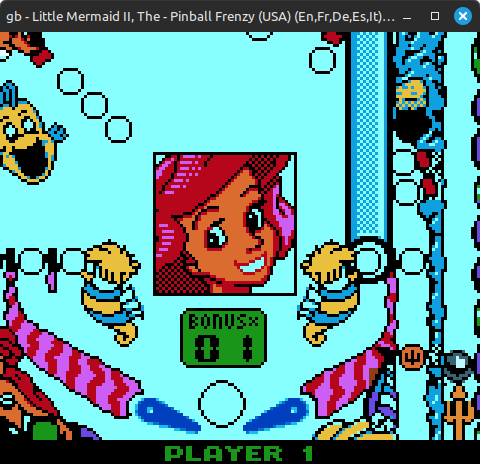
Well, enter The Little Mermaid II: Pinball Frenzy.
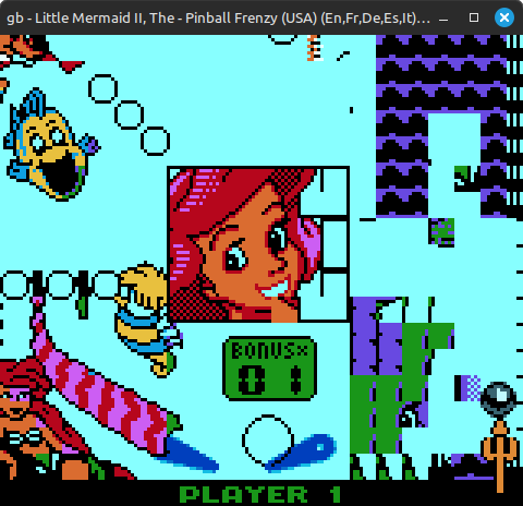 The Little Mermaid II: Pinball Frenzy
Yep, this game initiates HDMAs during HBlank, and it depends on them copying the first chunk immediately - not at the next line.
Disassembly of the relevant game code that initiates HDMA:
|
|
It has a pair of STAT polling loops to wait until the beginning of an HBlank period, then it immediately sets up and initiates an HDMA. It does this quickly enough that the HDMA5 write always occurs during HBlank.
In most cases, this works fine if the HDMA doesn’t begin immediately - it will just copy its 16-byte chunk one line later than it does on actual hardware. The problem is that the game sometimes changes the VRAM bank right after it initiates the HDMA.
Game Boy Color has 16 KB of VRAM, but at any given time only 8 KB is mapped to $8000-$9FFF in the CPU address space. The VBK register controls which 8 KB half is mapped. This affects both regular CPU memory accesses and VRAM DMA.
If these HDMAs initiated during HBlank don’t begin immediately, whenever the game changes the VRAM bank between the HDMA5 write and the next line’s HBlank period, the HDMA will copy the 16-byte chunk into the wrong VRAM bank. This causes fairly extreme graphical corruption, as seen above.
Pan Docs is a great resource documenting how the Game Boy [Color] hardware works, but for the most part its target audience is homebrew developers rather than emulator developers. I think this is a case where that’s relevant - the warning was more “it’s unclear what happens if you do this” rather than “the hardware doesn’t allow this”. (And I further made a bad assumption about what the hardware does here.)
That said…it seems like it’s fine to initiate HDMA during HBlank? Initiating it late enough into HBlank will cause the first chunk transfer to run over into the next scanline, but since it only copies 16 bytes at a time, the 16-byte chunk will always finish copying before the PPU enters mode 3 (rendering) and starts blocking CPU/DMA access to VRAM. This is almost certainly in the realm of officially undocumented behavior though, and I can’t say for sure that it always works this way.
Fix is again moderately simple: an HDMA5 write during HBlank with bit 7 set should initiate HDMA and immediately transfer the first 16-byte chunk (which happens to be the only chunk in this case).
F1 Championship Season 2000
For more officially undocumented behavior, Pan Docs has a note that VRAM DMA terminates early if the VRAM destination address overflows:
If the transfer’s destination address overflows, the transfer stops prematurely. The status of the registers if this happens still needs to be investigated.
I originally implemented this by forcing the address to the $8000-$9FF0 range on HDMA3/HDMA4 writes, ignoring the highest 3 bits and lowest 4 bits:
|
|
I then terminated VRAM DMA if the address ever incremented from $9FFF to $A000, “overflowing” out of VRAM into the cartridge RAM address range.
This is not correct!
This implementation caused freezing in F1 Championship Season 2000, which got stuck in an infinite loop here after you tried to start a race:
|
|
It’s waiting for the length in HDMA5 to read 0, which never happened.
Immediately before it entered this loop, it initiated an HDMA with destination address $9960 and length $7F ($800 bytes), which the emulator terminated as soon as the destination address reached $A000. So the length never reached 0 - it stayed at whatever it was when the emulator incorrectly terminated the HDMA.
The correct behavior is that the destination address should always wrap within $8000-$9FFF. If the address increments from $9FFF to $A000, DMA should start copying into the beginning of the current VRAM bank - the DMA should not terminate.
There is one case where overflow does terminate VRAM DMA: when the full 16-bit destination address overflows from $FFFF to $0000. The hardware ignores the highest 3 bits when copying into VRAM, but they are apparently used for this overflow check. I’m not aware of any games that depend on emulating this behavior but it has been verified on actual hardware.
NASCAR 2000
NASCAR 2000 was playable but had heavily corrupted background graphics, e.g. on the title screen here:
 NASCAR 2000
I originally suspected some bug related to palette RAM access and spent some time down that rabbit hole, but no, it’s HDMA again.
This game also counts lines but in a slightly different way than Pokemon Crystal does. It first does this to time initiating the HDMA, shortly after returning from its VBlank interrupt handler (so near the end of VBlank):
|
|
|
|
The first loop waits until the scanline is less than 0x80 / 128, and then the second loop waits until the scanline is greater than or equal to 0x1F / 31. This doesn’t work as intended in the general case, but it works where this code is executed: shortly after returning from the game’s VBlank interrupt handler, which begins to execute at the start of line 144. When jp start_hdma executes, the PPU has just started line 0x1F / 31.
Note that the HDMA length is fixed at 0x38 (0xB8 & 0x7F).
After initiating the HDMA, it loads some constants into registers and then executes another wait loop:
|
|
It waits until the PPU reaches line 0x57 / 87. This is exactly 0x38 lines after line 0x1F / 31, when the game initiated the HDMA. At this point the DMA length will be 0 which means it has one 16-byte chunk left to copy.
However, instead of letting the system copy that last chunk, the game immediately does this:
|
|
It…tries to start another HDMA before the first one finished?
This isn’t the same case as Pokemon Crystal because it sets the highest bit when it writes to HDMA5 (0xB7), so the write doesn’t terminate the first HDMA. Making that write a no-op causes the graphical corruption seen above.
As far as I can tell, this does effectively start a new HDMA by modifying the source address, the destination address, and the length in between 16-byte chunks. The HDMA status doesn’t literally go from idle to active, but for all intents and purposes it’s a new HDMA.
I already allowed software to make mid-HDMA changes to the addresses in HDMA1-4 (other games depend on this). Additionally allowing HDMA5 writes to change the length of in-progress HDMAs fixes this:

This again seems like confusion over the fact that HDMA ends at length 0x7F rather than 0x00, but the game programmers were able to get the hardware to do what they wanted anyway.
Toy Story Racer
I had to include one timing bug!
Here’s Toy Story Racer:
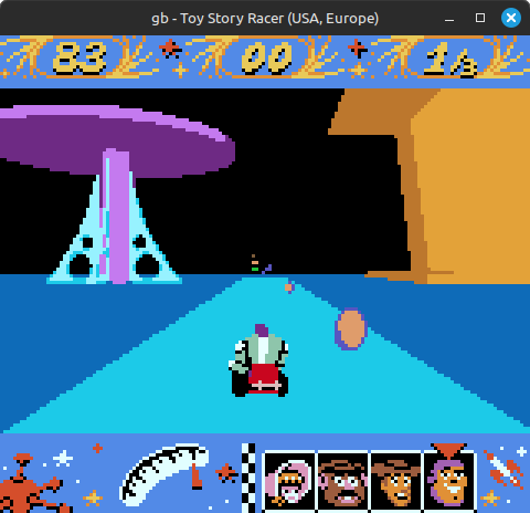 Toy Story Racer
It simulates 3D graphics by placing sprites on top of a streaming pre-rendered video that advances as you move through the track. It’s a pretty neat visual trick, and also technically impressive that they were able to get streaming video working even if at a low framerate (roughly 10-12 fps max).
The game mostly worked fine but every so often there would be a glitchy video frame, like this:
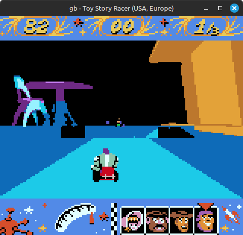
Naturally, this was HDMA-related.
The game pretty much constantly runs length-0 HDMAs to copy video frame data into VRAM, 16 bytes at a time. It uses a pair of loops polling STAT to ensure that it only tries to run one HDMA per line:
|
|
This code initiates HDMA at the beginning of each line, right when mode 2 begins.
Confusingly, after this it writes the source and destination addresses to HDMA1-4. It does this before HBlank, so these addresses will get used for the HDMA that it just initiated. It then goes back to these two loops to wait for the start of the next line.
There’s one big problem: the game doesn’t disable interrupts during these loops, and it has the STAT LY=LYC interrupt enabled here (Game Boy’s scanline interrupt).
This breaks the assumption that loop2 always ends close to the beginning of mode 2: if the STAT interrupt triggers while the code is in loop2, and then the interrupt handler returns midway through mode 2 or 3, the loop will immediately break and the game will start setting up an HDMA much later in the line than it’s supposed to. This has the potential to cause unexpected behavior if HBlank and thus HDMA begins while the game is in the middle of writing to HDMA registers, particularly since it writes to HDMA5 first and then writes to HDMA1-4.
However, in practice, the game almost always writes source and destination addresses that are exactly 16 bytes higher than the previous HDMA’s addresses, so it’s writing the same values that were already in the HDMA1-4 registers after the previous HDMA finished. It doesn’t matter that HDMA can start before the game has written to all 4 registers - it won’t change where the HDMA copies to or from.
So, what caused the glitch pictured above?
Short version, a timing bug related to writing to HDMA2 or HDMA4 right at the beginning of HBlank while HDMA is active.
Basically, I have logic to check whether the CPU should halt because of an active VRAM DMA, but that check was only performed once per instruction: at the beginning. This is fine for GPDMA because it always begins immediately after an instruction that writes to HDMA5, but this is not fine for HDMA. HDMA can begin mid-instruction if HBlank begins while the CPU is executing an instruction that’s longer than 1 M-cycle. Such as, say, an ldh [$52], a instruction: 3 M-cycles, with the memory write occurring on the last M-cycle.
This makes it possible for the following sequence of events to occur:
- CPU begins executing
ldh [$52], ainstruction (write to HDMA2) - HBlank begins; HDMA copies its first 1 or 2 bytes
- CPU executes final cycle of
ldh [$52], aand clobbers the low byte of the HDMA source address - CPU halts before fetching next instruction
- HDMA copies the remaining 14-15 bytes using a misaligned source address ($xxx0 instead of $xxx1/$xxx2)
The same thing can happen with writing to HDMA4 and clobbering the low byte of the destination address.
Through enabling some targeted logging I was able to confirm both that this was happening and that it only happened while copying a frame with a noticeable glitch.
This also means that HDMA wasn’t always halting the CPU for as many cycles as it should, though that’s much less of an issue than allowing the CPU to clobber the source or destination addresses after an HDMA chunk begins.
Amusingly, this bug wouldn’t have affected the game if I had HDMA copy each 16-byte chunk all at once instead of trying to go byte by byte while incrementing the same internal address fields that HDMA1-4 writes modify. I believe it’s even totally fine to do so since the CPU is halted during HDMA and HDMA’s VRAM writes will never get blocked by the PPU, though this is not true for GPDMA.
Anyway, I fixed this by adding an additional check in my function that advances all non-CPU components by 1 M-cycle: If a VRAM DMA is actively copying, continue to advance all non-CPU components cycle by cycle until the DMA chunk finishes (or the entire DMA for GPDMA). This allows HDMA to effectively halt the CPU mid-instruction, preventing the CPU from clobbering any mid-chunk state.