This is the sixth in a series of posts on emulating the main Sega Genesis sound chip, the YM2612.
This post will cover the hardware timers, the LFO (low frequency oscillator), and synthesized effects powered by the LFO.
Timers
The hardware timers are not directly related to the LFO, but this seems as good a place as any to cover them.
For the most part, the timers are purely for use by software. They do not affect any details of sound generation unless CSM is enabled, which I will overview a bit later in this post.
The YM2612 has two timers: a fast timer (Timer A) and a slow timer (Timer B). These are connected to an interrupt line, but the Genesis does not connect the YM2612’s interrupt line to anything, and there is also no way for software to read the current timer counter values. The only way for software to get feedback from the timers is by polling the timer overflow flags in the YM2612’s read port at $4000.
Games that use the timers typically use them only for audio timing, so music will play at the wrong speed if timer emulation is way off, and it usually won’t play at all if the timers aren’t emulated. Two examples of games that use the timers like this are Earthworm Jim (Timer A) and Ecco: The Tides of Time (Timer B).
The YM2612’s timers tick at half the rates listed in the YM2608 manual:
- Timer A: 1 tick per 144 master clock cycles / 24 internal cycles / 1 sample
- Timer B: 1 tick per 2304 master clock cycles / 384 internal cycles / 16 samples
“Master clock cycles” here refers to the YM2612’s master clock, which in the Genesis is the ~7.67 MHz 68000 CPU clock. This gives Timer A a frequency of ~53267 Hz and Timer B a frequency of ~3329 Hz.
Each timer supports a configurable interval, Timer A a 10-bit interval and Timer B an 8-bit interval. This value determines how frequently the timer overflows:
- Timer A: Overflows every (1024 - interval) timer ticks
- Timer B: Overflows every (256 - interval) timer ticks
Yes, it’s really a frequency rather than an interval since higher values make the timer overflow more frequently, but documentation refers to it as “interval” so I’m going to stick with that name.
Registers
The timers are configured using the following registers:
- $24: Timer A interval, highest 8 bits
- $25: Timer A interval, lowest 2 bits (Bits 0-1)
- $26: Timer B interval
- $27: Timer control
- Bit 0: Timer A enabled/loaded (“LOAD” in manual)
- Bit 1: Timer B enabled/loaded
- Bit 2: Timer A overflow flag enabled (“ENABLE” in manual)
- Bit 3: Timer B overflow flag enabled
- Bit 4: Clear Timer A overflow flag (write 1 to clear) (“RESET” in manual)
- Bit 5: Clear Timer B overflow flag
- Bits 6-7: Channel 3 per-operator frequency mode (01 / 10 / 11) and CSM (10)
The timer overflow flags are exposed in the lowest two bits of the YM2612’s read port:
- Bit 0: Timer A overflow flag
- Bit 1: Timer B overflow flag
- Bit 7: Busy flag
Operation
Timer A ticks once per sample, a rate of roughly 53267 Hz. Timer B has an internal divider such that it ticks once every 16 samples, e.g. it does something like this on every sample:
|
|
Each timer has its own internal counter, a 10-bit counter for Timer A and an 8-bit counter for Timer B. Each timer tick increments the internal counter. When the counter overflows to 0, it’s immediately reloaded with the software-configured interval, and the timer sets its overflow flag if it’s enabled (via bits 2 and 3 in register $27).
Taking Timer A as an example, ticking the timer might look something like this:
|
|
Timer B works very similarly, only its counter is 8-bit instead of 10-bit, and it has its internal divider such that it only increments the counter once every 16 samples.
Once an overflow flag is set, it remains set until software clears it by writing 1 to the corresponding clear bit in register $27 (bits 4 and 5).
The timers seem to only tick when the corresponding LOAD bit is set (bits 0 and 1 in register $27). At the very least, the overflow flag will never get set when a timer’s LOAD bit is clear.
When a LOAD bit changes from 0 to 1, that timer’s internal counter is immediately reloaded with its interval in addition to enabling the timer.
Changing the timer interval does not immediately affect the timer’s internal counter! Timer counters are only reloaded when they overflow or when the LOAD bit changes from 0 to 1.
Some documentation (including official documentation) claims that Timer A interval changes do not take effect until after the low bits are written, similar to the phase generator frequency registers. This is not accurate; writing to either half of the Timer A interval will immediately change those interval bits. They will be used starting from the next counter reload.
The last thing to note with the timers is that in actual hardware there is usually a 1-sample delay on changes to the LOAD bit taking effect, for both timers. This is because internally, each timer latches its LOAD bit almost immediately after it performs its counter/divider increment. I am not sure if any games depend on this for correct behavior.
CSM
CSM is a mode that was meant for speech synthesis. As far as I know, nothing uses it except for test ROMs that were designed to try and figure out how it works.
CSM is enabled by writing to the timer control register ($27) with bit 7 set and bit 6 clear, i.e. value & 0xC0 == 0x80. This also enables Channel 3’s per-operator frequency mode.
It seems like the main thing CSM does is automatically key on then key off all four of Channel 3’s operators whenever Timer A overflows. This is done in such a way that it has no effect on operators that are already keyed on by software. It effectively forces the operators’ key on/off states to “on” for a very short time, which does nothing to operators that are already keyed on.
This only does anything useful if all four operators have their attack rate set to 31 (the max) so that envelope attenuation is guaranteed to drop to 0 at each automatic key on, regardless of frequency.
Timer A’s LOAD bit must be set to 1 for CSM to do anything. It does not matter whether Timer A’s overflow flag is enabled.
LFO
The YM2612 has an LFO (low frequency oscillator) that powers vibrato effects (frequency oscillation) and tremolo effects (amplitude oscillation). This is a single LFO shared across all channels and operators.
Internally, the LFO is pretty much just a very slow timer with a configurable frequency. It contains a 7-bit counter that increments once per LFO clock. Vibrato and tremolo both use the current 7-bit counter value to determine the amount of the frequency or amplitude adjustment.
The supported oscillation rates range from ~3.85 Hz to ~83.23 Hz, this being the the frequency of a full 128-step oscillation. The single-step tick rate ranges from ~493 Hz to ~10653 Hz, with more granular options at the lower end.
Registers
The LFO itself is controlled using a single register:
- $22: LFO frequency (Bits 0-2) and LFO enabled (Bit 3)
Disabling the LFO via $22 bit 3 resets the LFO counter to 0 and holds it there until the LFO is re-enabled. Vibrato and tremolo can still be active while the LFO is disabled - they will just always read the LFO counter as 0, so the effect won’t oscillate.
Other registers control vibrato (LFO Frequency Modulation) and tremolo (LFO Amplitude Modulation):
- $60-$6F: LFO AM enabled (Bit 7) and envelope decay rate (Bits 0-4)
- $B4-$B6: LFO FM sensitivity (Bits 0-2), LFO AM sensitivity (Bits 4-5), and L/R panning flags (Bits 6-7)
Frequency
The LFO supports 8 different frequencies, selected using the lowest 3 bits of register $22. These are the frequency values from the YM2608 manual:
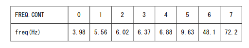
However, these numbers are based on an 8 MHz master clock, so the frequencies are a bit lower in the Genesis which gives the YM2612 a ~7.67 MHz master clock. It’s straightforward to compute the clock divider for each of these frequencies, for example frequency 0:
|
|
So, when frequency is set to 0, the LFO counter should increment every 109 samples…if this value is correct, which it’s not.
Doing this for all 8 frequencies gives the following 8-entry table:
|
|
However, these values are all off by one compared to the table in actual hardware, which is this:
|
|
Either the YM2608 manual is wrong here or the values are different between YM2608 and YM2612. I do not know which, but the second table has been confirmed in actual YM2612 hardware. I originally thought that maybe divider N actually means (N+1) samples between LFO counter increments, but that does not seem to be the case - a divider of 108 does mean that the LFO counter should increment every 108 samples.
So, a basic LFO implementation might look something like this:
|
|
I am not sure this handles frequency changes exactly correctly in terms of timing, but that’s not something that games are really sensitive to. It’s not common to frequently change the LFO frequency.
That is pretty much all there is to the LFO itself. The more interesting part is how operators use the LFO to create vibrato and tremolo effects.
Vibrato
Vibrato is when a note’s frequency (i.e. pitch) oscillates slightly over time, which creates a vibration-like sound. For a toy example, here is a 400 Hz sine wave with a synthesized vibrato effect:
The oscillation rate and the magnitude of the frequency variation together determine what the effect sounds like.
In the YM2612, each channel has a 3-bit LFO FM sensitivity value that controls the level of the vibrato effect. A value of 0 disables vibrato, while any other value selects 1 of 7 different levels of intensity. Higher vibrato levels produce a larger variation in frequency. The LFO frequency controls the frequency oscillation rate.
The channel’s vibrato level is used for all 4 of its operators. There is no way to use different levels of vibrato for different operators within a channel, or to selectively enable vibrato for only some of a channel’s operators.
The YM2612’s vibrato effect is true frequency modulation, not phase modulation. It modifies operators’ F-numbers as they go into the phase generator. (This is despite the YM2608 manual occasionally referring to it as PM / phase modulation…)
Vibrato can either add or subtract from the base F-number. The exact frequency change amount is calculated as a multiple of the base F-number.
In Theory
The YM2608 manual contains this table of FM sensitivity (“PMS” here) to “modulation level”:
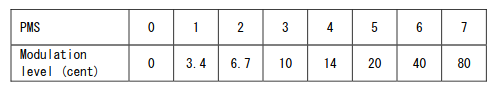
These values are in cents, a logarithmic scale where 100 cents is equal to the distance between two adjacent notes on a 12-tone scale (e.g. between D and D#/E♭ within the same octave). In other words, YM2612 vibrato can oscillate the frequency within anywhere from 3.4% of a note (vibrato level 1) to 80% of a note (vibrato level 7).
Given a frequency F and a cent value C, the frequency F’ that is C cents away from F is computed using this formula:
F’ = F ⋅ 2C/1200
At a high level, this formula comes from the facts that increasing by an octave is a 2x increase in frequency and that there are 1200 cents in an octave.
Applying this formula to the values in the above table gives the following 8 multipliers in linear scale:
|
|
These are the upper limits of the frequency oscillation range for each vibrato level, as a multiple of the base frequency. The lower limits are the same distance away from 1, but on the opposite side:
|
|
These multipliers are roughly accurate in terms of how the chip logically applies vibrato, but of course the YM2612 has a very particular way of performing the calculation using lookup tables, bit shifts, and additions rather than directly performing any multiplication operations.
In Practice
There are 3 inputs to the vibrato calculation:
- 3-bit vibrato level (FM sensitivity)
- Highest 5 bits of the 7-bit LFO counter (lowest 2 bits are used only for tremolo)
- Highest 7 bits of the 11-bit F-number
The vibrato level and LFO counter together determine the effective frequency multiplier to apply to F-number. The vibrato level determines the frequency oscillation range and the LFO counter determines the current position within the range.
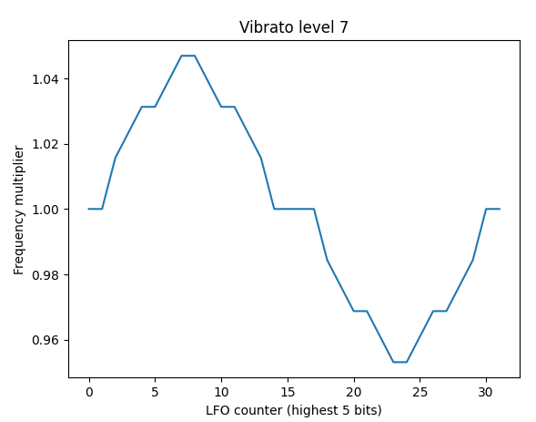 Effective frequency multipliers at max vibrato level
First, note that the final output of the vibrato calculations is a 12-bit frequency value, not 11-bit like the input F-number. The chip adds an extra bit of precision while calculating vibrato, so the output is an 11.1 fixed-point decimal number. This extra bit gets truncated when the phase generator applies block, described in more detail below.
Given a vibrato level, bits 2-5 of the LFO counter determine the magnitude of the frequency change, and the highest bit determines whether to increase or decrease frequency.
There are a few different ways to emulate how the hardware performs the frequency multiplication, but I think the simplest is probably to use a single multiplier lookup table and perform bit-by-bit multiplication with F-number. Going bit by bit is necessary in order to ensure that the calculations exactly match actual hardware, which performs this calculation using only bit shifts and additions.
To start, here is the 8x8 lookup table:
|
|
You could omit the level 0 row since the values are all 0, i.e. vibrato level 0 will never change an operator’s frequency.
These values are the amount that should be added or subtracted from the 12-bit left-shifted F-number if the highest F-number bit is set. If the second-highest bit is set, half this amount should be added/subtracted. Third-highest bit, one-quarter this amount. And so on. Since the highest value is less than 27, the lowest 4 bits of the 11-bit F-number will never affect the final result.
For example, at vibrato level 7, the effective frequency multipliers are roughly equal to:
|
|
Every value in the table is either zero, a power of two, or a sum of two different powers of two. This is because actual hardware implements this multiplication using bit shifts and additions rather than using this exact lookup table.
This table is indexed into first using the 3-bit vibrato level and then using a second 3-bit index derived from bits 2-5 of the LFO counter, similar to how the chip computes the lookup index for the log2-sine table:
|
|
A simple implementation of bit-by-bit multiplication might look something like this:
|
|
Then, the highest bit of the LFO counter determines whether to add or subtract from the base F-number (left shifted 1):
|
|
And then finally, the modulated F-number should be masked to 12 bits, because overflow is possible when increasing frequency:
|
|
After this, the rest of the phase generator calculations proceed as normal, only with an extra right shift while applying block that removes the 12th frequency bit. The calculation was originally this:
|
|
With vibrato in place, it should change to this:
|
|
The rest of the phase generator calculations remain unchanged.
Detune and the envelope generator’s key scaling should continue to compute key code using the base F-number, not the frequency modulated F-number.
For a game example, Ecco the Dolphin and its sequel use both vibrato and tremolo for many of their sound effects and musical instruments. Ecco’s charge sound effect in particular uses both vibrato and tremolo at max level.
Here is the sound effect without either vibrato or tremolo emulated:
And here it is with vibrato (still no tremolo):
If you’ve played the game then you know that’s not exactly what it’s supposed to sound like, but it’s much closer than the first recording.
Tremolo
Thankfully, tremolo is much simpler than vibrato.
In general, tremolo refers to musical effects that create a trembling-like sound. Tremolo is closely related to vibrato but they are not the same thing.
Here is a 400 Hz sine wave with a synthesized tremolo effect:
For comparison, here’s the synthesized vibrato example again:
In the YM2612 specifically, tremolo is synthesized by using the LFO to oscillate volume/amplitude over time. It does this by adding attenuation to the envelope generator’s output, before it’s combined with the phase generator’s output.
There are 3 inputs to the tremolo calculations:
- Tremolo / LFO AM enabled, configured per operator
- Tremolo level / LFO AM sensitivity (2-bit), configured per channel
- Current 7-bit LFO counter
Unlike vibrato, tremolo can be enabled or disabled per-operator, not only per-channel. All 4 of a channel’s operators must use the same tremolo level, but it’s possible to selectively enable tremolo for only some of the 4 operators.
At max tremolo level, tremolo adds between 0 dB and roughly 11.8 dB of attenuation. The other tremolo levels simply downshift the amount of added attenuation:
- Level 2: Half as much attenuation as level 3 (max ~5.9 dB)
- Level 1: One-eighth as much attenuation as level 3 (max ~1.4 dB)
- Level 0: Tremolo disabled
Tremolo only has any effect on an operator if the channel’s tremolo level is non-zero and that particular operator has tremolo enabled.
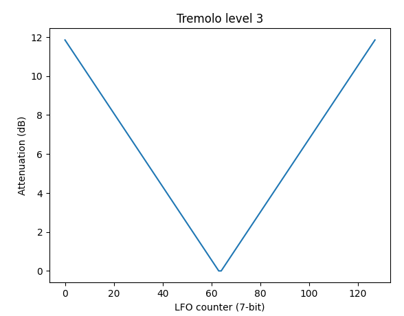 Added attenuation at max tremolo level
Note that added attenuation is highest at LFO counter 0 and lowest halfway through the oscillation. I believe some games depend on this due to enabling tremolo while the LFO is disabled, which holds the LFO counter at 0.
Tremolo works by taking the 7-bit LFO counter and transforming it into a 6-bit value, which is then interpreted as a 1.5 fixed-point decimal number that represents a log2 attenuation value. This is a bit shift away from being on the same scale as the envelope generator’s output.
The first half of the oscillation computes this 6-bit value by simply inverting the lowest 6 bits of the LFO counter, and the second half uses the lowest 6 bits as-is:
|
|
This value is then left shifted by 1 to convert it to the same scale as the envelope generator’s 4.6 fixed-point output:
|
|
And finally, it’s right shifted based on the channel’s tremolo level:
|
|
If tremolo is enabled for the operator, this is then added to the envelope generator’s output alongside total level:
|
|
And that’s it! Emulating tremolo alongside vibrato gets the Ecco charge sound effect to sound correct:
Tremolo is particularly powerful when used with modulators because it automatically oscillates the level of phase modulation over time, making it possible to create very complex instrument sounds.
To Be Continued
The only thing left is the envelope generator’s SSG-EG functionality, which I saved for last only because it’s the least-used YM2612 feature aside from CSM. Very few games are known to use it, probably because it was officially undocumented.