This is the fifth in a series of posts on emulating the main Sega Genesis sound chip, the YM2612.
This post will cover a few aspects of the YM2612’s audio hardware, particularly the DAC (digital-to-analog converter), that are not strictly related to sample generation but do noticeably affect the sound of the final output.
Panning
Each of the YM2612’s 6 audio channels can only output a single sample at a time, but the YM2612 supports stereo audio output via panning individual channels.
Each channel has two panning bits in registers $B4-$B6, one for enabling L output (Bit 7) and one for enabling R output (Bit 6). Other bits in these registers are used to configure LFO FM (vibrato) and AM (tremolo) sensitivity.
Panning is all or nothing. If a panning bit is set to 1, the channel outputs its sample value. If it’s set to 0, the channel is muted.
As I mentioned back in the first post, the DAC channel respects the Channel 6 panning bits. When the DAC channel is enabled, it works by running Channel 6 normally but then replacing Channel 6’s generated sample at the output stage, right before applying panning.
All panning bits should be initialized to 1 at power-on! A few games depend on this due to not properly initializing panning, such as After Burner II.
It’s worth noting that in actual hardware, different console revisions have different levels of support for stereo audio output:
- Model 1: TV out supports mono audio only; headphone jack supports stereo audio
- Model 2: Supports stereo audio
- Model 3: Mono audio only
Removing stereo audio in the Model 3 might seem strange if you’re not already familiar with what the Model 3 is: a budget model produced by Majesco several years after the Saturn released. This model also removed the connections necessary for Sega CD and 32X to work, among other changes (some of which break games, e.g. Gargoyles does not work on the Model 3 due to a bus behavior change that affects the 68000 TAS instruction).
If you wanted to emulate mono audio output, you could simply average the final mixed L and R samples instead of outputting them separately.
DAC Quantization
While operators output signed 14-bit PCM samples, the YM2612 only has a 9-bit DAC. The lowest 5 bits of each channel’s output sample get truncated during output, and not emulating this truncation makes audio output sound a little too clean and perfect compared to actual hardware.
The YM2612 multiplexes channels through its DAC instead of mixing them. In an emulator, if you’re mixing the channels, this means that you should quantize before mixing rather than after.
Relatedly, for algorithms with multiple carriers, the carrier outputs are summed using a 9-bit accumulator rather than a 14-bit accumulator. An emulator should actually quantize carrier outputs, not channel outputs. These are equivalent for the single-carrier algorithms (0-3) but not for the multi-carrier algorithms (4-7).
You could implement quantization by leaving the calculations as 14-bit but masking out the lowest 5 bits of every input, e.g. for algorithm 7:
|
|
You could also simply right shift everything by 5 to discard the lower bits:
|
|
You may want to implement an option for whether to emulate this quantization, since not emulating it is less accurate but can sound better in some games. If quantization is implemented by leaving the calculations in 14-bit but masking out the lowest 5 bits, the option to not emulate quantization only needs to change the mask to !0.
One example of where quantization noticeably affects the sound is the jingle that plays on the Konami logo screen in many of Konami’s games. Not emulating quantization makes the jingle sound much less noisy than it does on actual hardware. Example from Castlevania Bloodlines:
It’s particularly noticeable during the fade-out at the end.
This is getting ahead a bit, but the effects described later in this post also significantly affect how this jingle sounds:
Ladder Effect
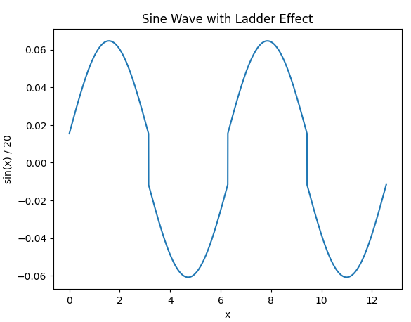
The YM2612’s DAC introduces a form of crossover distortion into its output, commonly known as the “ladder effect”. Some games have audio designed around this effect, and the difference between emulating it and not emulating it is very noticeable in these games. The Streets of Rage games and After Burner II are probably the most well-known examples.
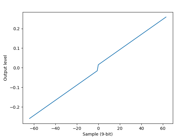
I cannot explain the hardware or electrical reasons why this occurs, but I can describe how it manifests. The YM2612 DAC’s output level is fairly linear for 9-bit samples from -256 to -1, as well as from 0 to +255, but there is a large non-linear jump between -1 and 0.
This effectively amplifies low-volume waves so that they sound much louder than they would if the DAC’s output was linear all the way from -256 to +255, while also adding a bit of audio noise. It technically amplifies higher-volume waves as well, but the effect becomes less and less noticeable as wave volume increases.
 Ladder effect
 Low-volume sine wave with ladder effect
The most accurate emulation of the ladder effect thus far is the implementation originally created by nukeykt for Nuked-OPN2, a cycle-accurate YM2612 and YM3438 emulator that is largely a direct translation of the hardware into C. Most other emulators that are still under active development have adopted some variation of this algorithm. There is some interesting discussion of Nuked-OPN2’s ladder effect emulation in this Genesis Plus GX pull request to integrate Nuked-OPN2.
There are two components to Nuked-OPN2’s ladder effect emulation.
First, in actual hardware, the output voltage gap between samples -1 and 0 is twice as large as it would be if the DAC was completely linear. This is emulated by adding 1 to all non-negative samples.
Second, for each channel, the YM2612 actually outputs to its DAC in groups of 4 slots. The first slot is for the channel’s output sample, and the other three slots are supposed to be silence, i.e. the output level for sample 0. However, it seems like the “silence” slots actually output the voltage level for either -1 or 0, pulled in the direction of the sample’s sign bit. And again, the voltage gap between -1 and 0 is twice as large as it should be, so this is emulated by having the silence slots output either -1 or +1.
 Emulated DAC output for non-negative samples
 Emulated DAC output for negative samples
These silence slots appear to output the sample’s sign bit even if the channel is muted via the L/R panning flags in registers $B4-$B6. Muting the channel this way simply turns the sample slot into a fourth “silence” slot, which will output -1 if the sample is negative and +1 if it’s non-negative. This adds audio noise whenever a channel is not outputting to both the L and R outputs, if the channel’s sample output is not a constant zero.
Non-cycle-accurate emulators don’t emulate these output slots directly. Instead, they usually do the following, for each of the 6 YM2612 channels and for each of the 2 output channels (L/R):
- If the channel is muted, output a fixed level of either +4 or -4 depending on the sample’s sign bit
- If the channel is not muted, add +4 to non-negative samples and -3 to negative samples
This produces an equivalent result to aggregating over each group of 4 slots. In aggregate, the output level gap between samples -1 and 0 is actually eight times what it would be if the DAC was completely linear. This sets a fairly high volume floor on the chip’s audio output.
Note that all of the above values are as 9-bit samples. If you’re generating output using 14-bit samples, you need to left shift these values by 5.
Here is an example song where ladder effect emulation makes a very noticeable difference, the Streets of Rage 2 intro:
And for completeness, here’s a version that also applies a low-pass filter:
The ladder effect is not present on consoles that have a YM3438 instead of a discrete YM2612, so it is probably worth having an option for whether or not to emulate this behavior. Not emulating the distortion is more accurate to consoles with a YM3438.
Low-Pass Filtering
Rather than just regurgitate something I’ve previously written, here’s a previous post I wrote on this topic: Genesis & Sega CD - Audio Filtering
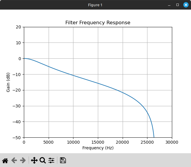
 Frequency response for a 3.39 KHz first-order Butterworth IIR low-pass filter, source frequency 53267 Hz
The low-pass filter is part of the Genesis hardware rather than the YM2612 hardware, unlike the DAC that causes the above two effects. The filter applies to both YM2612 output and PSG output. This is notable because there are many games where the low-pass filter significantly affects the sound of the PSG’s noise channel.
A first-order 3.39 KHz or 2.84 KHz low-pass filter is most accurate to the consoles that are considered to have the best audio quality. These filters will still let a lot of higher-frequency audio through - they apply barely more than 20 dB of attenuation at 20000 Hz, the upper edge of the audible frequency range - but they will attenuate higher frequencies (treble) much more than lower frequencies (bass), which has the effect of emphasizing bass. Some game audio is clearly designed around this.
This is another area where you might want to offer a variety of different options. Later console revisions have a second-order low-pass filter that makes audio output sound much more muffled compared to Model 1 VA0-VA6 consoles. Some prefer the sharper sound produced by not performing any low-pass filtering, or using a low-pass filter with a very high cutoff frequency (e.g. 15 KHz or 20 KHz).
Here’s a comparison of the Seven Force boss theme from Gunstar Heroes, re-recorded after fixing some bugs in my YM2612 implementation that caused the jingling to sound slightly wrong:
And Go Straight from Streets of Rage 2, just because it’s a very good song that I personally think benefits from the filter (mainly because it heavily attenuates the PSG’s noise channel):
And for one more example, here’s the Sonic 2 recording from the end of the previous post, followed by another recording that emulates DAC quantization + ladder effect + low-pass filtering:
It’s definitely subjective which sounds better, but I think the second recording sounds much closer to actual hardware! The low-pass filter is what makes the biggest difference most of the time.
To Be Continued
The next post will cover the LFO and the timers, which are the last pieces of the hardware that are not yet emulated (aside from SSG-EG). While this is less exciting and some games don’t use them at all, emulating them is required to get correct audio in many games.