This is the fourth in a series of posts on emulating the main Sega Genesis sound chip, the YM2612.
This post will describe how the chip computes operator and channel outputs given the phase generator and envelope generator outputs. This will be enough to get mostly correct-sounding audio in some games!
Operator Output
Operator output calculation is where the chip gets really clever in terms of using lookup tables and fixed-point math to avoid needing to directly perform complex calculations like sines, exponents, logarithms, divisions, or even multiplications.
Each operator’s phase generator outputs a 10-bit value that represents a sine wave phase on a scale from 0 to 2π.
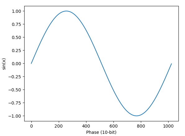 Phase to sine
Each operator’s envelope generator outputs a 10-bit value that represents an attenuation level on a logarithmic scale from 0 dB to roughly 96 dB. To be precise, it’s a 4.6 fixed-point decimal number in log2 scale: an attenuation value of N functions as an amplitude multiplier of 2-N.
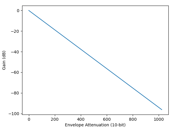 Attenuation to decibel gain
The chip manages to combine these two values and produce a signed 14-bit PCM sample using only lookup tables, bit shifts, and additions. This section will describe how.
Log2-Sine
The chip’s main trick is that instead of computing sine from the phase generator’s output, it computes a log2-sine value that is only a bit shift away from being on the exact same logarithmic scale as the envelope generator’s output. This makes it possible to apply envelope attenuation using an addition operation in log scale instead of multiplication in linear scale.
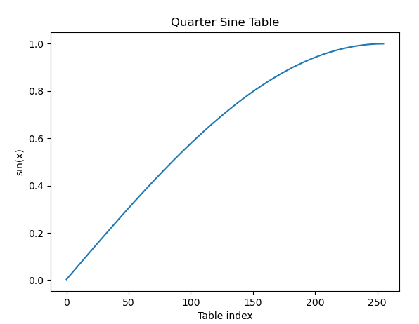
Naturally, this computation is performed using a lookup table. Specifically, a 256-entry lookup table that covers one quarter of the sine wave.
The chip only needs a quarter-sine table because the second half of a sine wave oscillation is simply the first half inverted, and the second quarter is simply the first quarter mirrored horizontally (i.e. mirrored across the y-axis).
Concretely, if you have a phase value from 0 to 2π, you can rewrite the sine calculation to only require computing sine values for phases between 0 and π/2:
sin(x) for x ∈ [0, π/2)
sin(π - x) for x ∈ [π/2, π)
-sin(x - π) for x ∈ [π, 2π)
The chip takes the 10-bit phase, puts the highest bit off to the side to use later as a sign bit, and then computes a lookup table index from 0 to 255 using the lower 9 bits:
|
|
0x1FF - (phase & 0x1FF) is equivalent to !phase & 0xFF if phase is between 0x100 and 0x1FF, so the subtraction is not strictly necessary.
The lookup table itself contains inverted log2-sine values: -log2(sin(x)), where x is on a scale from roughly 0 to π/2. The values are 12-bit, 4.8 fixed-point decimal numbers.
The inversion converts from negative gain values to positive attenuation values. log(N) is always negative when N is between 0 and 1, so -log2(sin(x)) is always positive when x is between 0 and π/2.
The lookup table’s x scale is actually slightly offset, presumably to ensure that the second quarter-sine correctly mirrors the first quarter-sine, as well as to avoid needing to compute log2(0) which is -∞. Index 0 represents (1/512 * π/2), and index 255 represents (511/512 * π/2). Generalized, the x formula is:
x = (2n + 1)/512 * π/2
…where n is the table index from 0 to 255.
Given all this, constructing the lookup table is not too hard:
|
|
This code produces a bit-perfect match for the lookup table in actual hardware.
I’m using Rust’s LazyLock here which will execute the initializer the first time the variable is accessed, then reuse that value for all later accesses. Even on modern CPUs, the combined calculations are slow enough and the table is small enough that it’s beneficial to emulate the lookup table using, well, the same lookup table.
Visualized, first the sine values and then the actual table values:
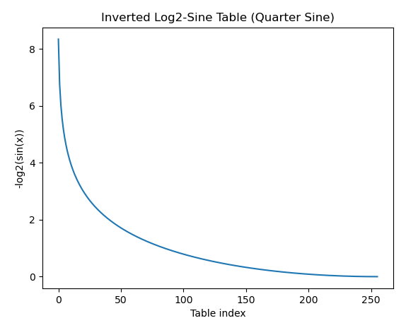
Note that the highest value is less than 16, so values will never exceed the upper limit of 4.8 fixed-point decimal.
Using this table, we can quickly compute an attenuation level in log2 scale given the lowest 9 bits of the phase generator’s output, with the exact same level of precision as actual hardware.
The envelope generator’s output is also an attenuation level in log2 scale, as a 4.6 fixed-point decimal number. This means that applying envelope attenuation is a simple bit shift and addition:
|
|
Addition in log scale is equivalent to multiplication in linear scale, but addition is much cheaper to perform in hardware.
This addition produces a 5.8 fixed-point decimal number that represents the magnitude of the final sample output, but as attenuation in log2 scale instead of amplitude in linear scale.
Base 2 Exponentiation
The YM2612’s DAC needs the sample value on a linear scale, so the chip needs to convert from this log2 attenuation value. The way it performs this conversion is almost certainly the reason that it specifically uses log2 scale rather than decibels, plain log10, or some other logarithmic scale.
Mathematically, the calculation is simply 2-N, where N is the log2 attenuation value. This would be trivial if N was a plain integer, but it’s not - it’s a 5.8 fixed-point decimal number.
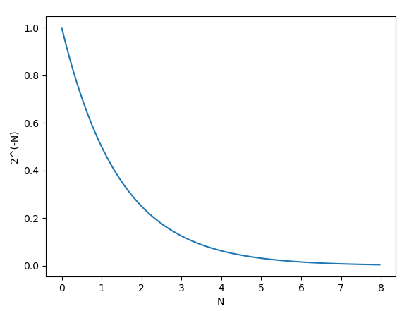
The chip implements this partially using a lookup table and partially using bit shifts. Logically, it separately computes 2-N for the 5 integer bits and the 8 fractional bits, and then multiplies the results together.
2-N = 2-int ⋅ 2-fract
First, the lookup table. This is a 256-entry lookup table containing 2-N for all 0.8 fixed-point decimal numbers, used to compute 2-fract for the 8 fractional bits. The table contains 11-bit values, 0.11 fixed-point decimal numbers.
The table is slightly offset such that each entry table[N] actually contains the value 2-(N+1)/256, not 2-N/256. As Nemesis notes in his post on this, this was probably done to avoid needing to store the 12th bit required to accurately represent 20, though there were other ways they could have worked around this without adding a 12th bit to the table values. The most notable effect of this offset is that the largest value in the table is roughly 0.9973, not 1.
Constructing the table is straightforward:
|
|
Visualized:
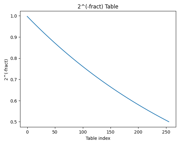
The value read from the table is always left shifted by 2, presumably to add a little more precision to the final output sample values. So the final result of 2-fract is a 0.13 fixed-point decimal number, but the lowest 2 bits are always 0.
Multiplying by 2-int is just a bit shift. For any non-negative integer N, multiplying by 2-N is equivalent to right shifting by N, so the final calculation is just:
|
|
That’s it! No actual multiplication operations or even addition; just a lookup table and bit shifts. The final output is interpreted as an unsigned 13-bit PCM sample.
Do be wary that if you’re using u16 values here, right shifting by int_part can overflow! You can avoid this by explicitly checking whether int_part is at least 13, in which case the sample output will always be 0:
|
|
You could also use a u32 value instead, since int_part will never be larger than 31.
This is why envelope generator outputs of 0x340 or higher mute the operator. 0x340 in 4.6 fixed-point decimal is exactly 13.
Finally, PCM Samples
The very last step is to apply the highest bit of the phase generator output as a sign bit, since that highest bit indicates whether the phase is in the positive half of the sine wave or the negative half:
|
|
And with that, we have signed 14-bit PCM samples!
This doesn’t sound hugely different from the output at the end of Part 3, but it’s much more accurate in that it uses the same level of precision as actual hardware, which (partially) fixes the audio sounding a little too clean:
For comparison, here’s the recording from the last post again:
There is an audible difference!
Anyway, it doesn’t sound like it, but this is actually really close to sounding much more like actual hardware! Let’s go the rest of the way.
Channel Output
Next step: combining operator outputs to produce channel outputs.
Channel output parameters are configured using a single register:
- $B0-$B2: Algorithm (Bits 0-2) and Operator 1 feedback level (Bits 3-5)
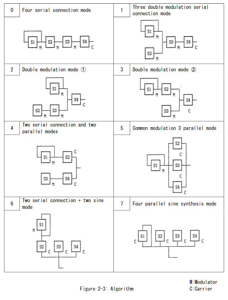
Here’s again the page from the YM2608 manual that describes the chip’s 8 algorithms:
Phase Modulation
Phase modulation produces very complex waveforms, particularly with 4-operator synthesis, but the way it works is quite simple: when an operator has a modulator input, it adds bits 1-10 of the modulator’s operator output to its own 10-bit phase generator output before performing the log2-sine table lookup. That is all it does, there’s no magic.
When an operator has multiple modulator inputs (e.g. Operator 4 in algorithms 2 and 3), it sums them and then adds bits 1-10 of the sum to its phase generator output.
Note that phase modulation does not actually modify the phase generator’s counter! This is why it’s really phase modulation rather than frequency modulation - it applies an offset to the phase generator’s output rather than modifying the phase generator’s frequency.
Mathematically, where the phase generator output is on a scale from 0 to 2π, modulator outputs are applied such that the maximum operator output causes a phase shift of roughly +8π and the minimum operator output causes a shift of -8π.
Software can narrow the range of possible phase shifts by using the modulator’s envelope generator to reduce the range of possible operator outputs, which will change the instrument sound.
Algorithms
Implementing the algorithms is pretty much just implementing the above diagram, with two quirks: operator evaluation order, and operator evaluation pipelining.
The first quirk is that operators are evaluated in the order 1->3->2->4, not 1->2->3->4 as you might expect. This means that if Operator 2 modulates Operator 3, Operator 3 will always phase modulate using Operator 2’s output from the previous sample cycle rather than its new output computed during the current sample cycle. This affects algorithms 0, 1, and 2.
The second quirk is that due to how operator evaluation is pipelined within the chip, if two operators A and B are evaluated consecutively, Operator A’s output is not yet available by the time Operator B reads modulator outputs for phase modulation. This means that if Operator A modulates Operator B, Operator B will always use Operator A’s output from the previous sample cycle. This affects algorithms 1, 3, and 5.
Full list of “delayed” modulator outputs:
- Algorithm 0: Operator 2 -> Operator 3
- Algorithm 1: Operator 1 -> Operator 3 and Operator 2 -> Operator 3
- Algorithm 2: Operator 2 -> Operator 3
- Algorithm 3: Operator 2 -> Operator 4
- Algorithm 5: Operator 1 -> Operator 3
Algorithms 4, 6, and 7 are not affected by evaluation order or pipelining.
It’s a very small difference compared to not properly emulating evaluation order or pipelining, but it’s worth noting since it’s not too hard to emulate it.
Here’s an example of what the algorithm implementation might look like for algorithm 3. For simplicity, this does not emulate evaluation order or pipelining:
|
|
The right shifts are because phase modulation only uses bits 1-10 of the modulator outputs. Bit 0 has no effect.
This is assuming that the operator clock() method takes in the pre-shifted modulator input(s):
|
|
For algorithms with multiple carriers, the carrier outputs are summed to generate the channel output. The sum should be clamped to signed 14-bit to match the scale of individual operator outputs. I’m not sure if this actually affects any games, but it’s been confirmed that actual hardware clamps rather than overflows if the sum exceeds the output range of a single operator.
Let’s try Sonic 2 again, with algorithms and phase modulation implemented:
Still not quite there, but that sounds a lot closer! Only some of the instruments are still wrong.
The last missing piece is operator 1 feedback.
Operator 1 Feedback
Operator 1 never has a modulator input in any of the 8 algorithms. Instead, it can uniquely phase modulate itself using its last two operator outputs. This feature is called feedback and it can be used with any of the 8 algorithms.
Feedback level is a 3-bit value. A feedback level of 0 means feedback is disabled, while any other feedback level phase modulates Operator 1 using the following value:
|
|
The (10 - feedback_level) shift is assuming that the modulation >> 1 shift is not applied to the feedback value. If you structure your code in such a way that the right shift by 1 is applied to both modulator outputs and the feedback value, you should shift by (9 - feedback_level) instead. It will be very audibly obvious if you shift by the wrong value.
It’s possible to mostly derive this formula from the YM2608 manual, but it’s missing one critical piece of information: the fact that feedback uses the average of the last two operator outputs. The manual implies that feedback only uses the last operator output, so you’d end up with prev_op1_output >> (9 - feedback_level), which is not accurate.
This table from the manual is helpful for gaining an intuition regarding what the feedback level represents:

These values indicate how much the maximum or minimum operator output should shift the phase.
When the feedback level is 6 for example, the maximum operator output should shift the phase by +2π and the minimum operator output should shift by -2π. Given that the phase generator’s output is unsigned 10-bit and represents 0 to 2π, this implies that feedback level 6 should bit shift the signed 14-bit operator output to signed 11-bit.
This generalizes to an arithmetic right shift of (9 - F) where F is the feedback level, but since the chip actually wants to use the average of the last two operator outputs, it right shifts their sum by 1 more to get (10 - F).
Anyway, that’s all there is to it! The feedback value simply takes the place of the modulator input(s) for Operator 1, since it never actually has a modulator input in any algorithm.
And with that:
There we go!
It still sounds too clean and sharp compared to actual hardware, but as far as the chip’s digital output, this is mostly correct. The chip isn’t fully emulated yet - the LFO and timers are still missing - but Sonic 2 doesn’t use any of the not-yet-implemented functionality, at least not in this song.
To Be Continued
The next post will cover several aspects of the audio hardware that significantly affect the digital-to-analog audio conversion, such as DAC quantization and a DAC distortion commonly known as the ladder effect. Emulating these is necessary to produce audio output that sounds like actual hardware.