This is the third in a series of posts on emulating the main Sega Genesis sound chip, the YM2612.
This post will describe how the ADSR envelope generators work.
ADSR
Each of the YM2612’s 24 operators has its own ADSR envelope generator that automatically adjusts the operator’s volume over time. Lower volumes reduce the amplitude of the generated sine wave.
ADSR stands for Attack, Decay, Sustain, Release. I’m going to reuse a diagram that I made for a previous post:
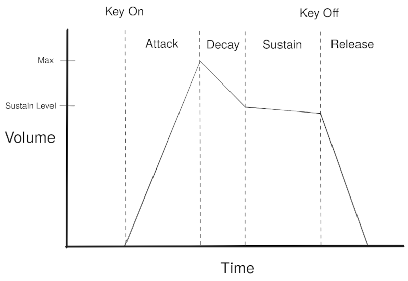
When an operator is keyed on, volume gradually increases to max (Attack).
Once volume reaches max, volume gradually decreases down to the sustain level (Decay).
Once volume reaches the sustain level, volume decreases indefinitely (Sustain), though normally at a slow rate - possibly zero, which would hold volume constant until key off.
When the operator is keyed off, volume also decreases indefinitely (Release), but typically at a faster rate than during Sustain phase.
Now, ADSR works a bit differently in the YM2612 because the envelope generators output attenuation values on a logarithmic scale rather than directly outputting volume multipliers. Higher attenuation means lower volume, and vice versa.
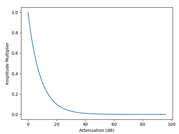 Attenuation to Multiplier
Attack phase decreases attenuation down to 0. Decay phase increases attenuation up to the sustain level. Sustain and Release phases both increase attenuation indefinitely, up to the maximum.
The YM2612’s envelope generators exponentially decrease attenuation during Attack phase and linearly increase attenuation during Decay, Sustain, and Release phases.
Envelope Generation
The envelope generators are not really that complicated, but they have a lot of details that are very important to get right or game audio will break in weird ways. They can be exceptionally difficult to debug if you get anything wrong because the envelope generators don’t only affect volume - they also affect instrument sounds due to phase modulation and feedback.
Each envelope generator ultimately outputs a 10-bit attenuation value. This value represents a 4.6 fixed-point decimal number: 4 integer bits, 6 fractional bits. Attenuation values are always non-negative.
This is not part of the envelope generator, but the envelope’s output A is applied as an amplitude multiplier of 2-A. The maximum attenuation value is slightly higher than 96 dB (decibels):
|
|
A change of 1 in the 10-bit attenuation value changes the effective attenuation by roughly 0.094 dB:
|
|
Here are some graphs that demonstrate that the attenuation values are on a logarithmic scale rather than linear:
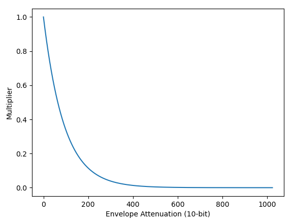 Attenuation to Amplitude Multiplier (Linear Y scale)
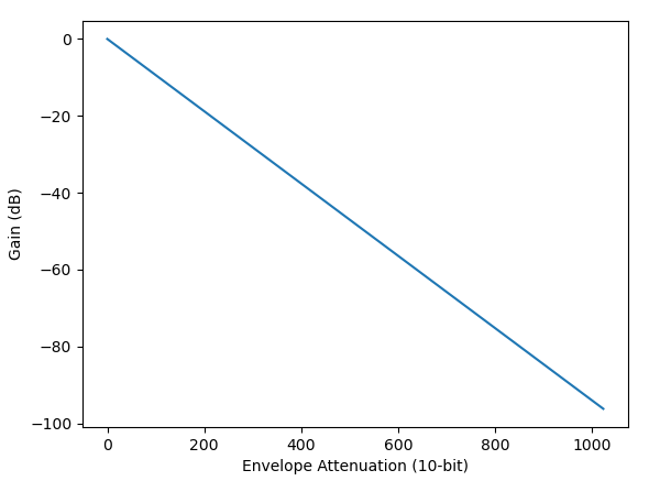 Attenuation to Decibel Gain (Logarithmic Y scale)
Using a logarithmic scale is a good thing in terms of envelope behavior because the logarithmic scale is significantly closer to how the human ear perceives differences in wave amplitude. Log scale also enables the chip to apply the amplitude/volume multiplier using an addition operation rather than a more expensive multiplication operation, which I will cover in detail in the next post.
As a side effect of how attenuation is implemented in the chip, any attenuation value above 0x340 / 832 (roughly 78 dB) ends up producing an amplitude multiplier of 0, which mutes the operator. This will be discussed a bit in the section on how operator outputs are computed.
The envelope generator itself simply computes and outputs these 10-bit attenuation values. It is not aware of the 2-A formula or what any particular value represents in decibels.
Inputs
The envelope generator has quite a lot of inputs:
- Attack rate (5-bit)
- Decay rate (5-bit)
- Sustain rate (5-bit)
- Release rate (4-bit)
- Sustain level (4-bit)
- Total level (7-bit), i.e. base attenuation
- Key scale level (2-bit)
- LFO AM enabled, i.e. tremolo
- LFO AM sensitivity (2-bit), i.e. tremolo level
LFO AM sensitivity is configured per-channel, everything else is configured per-operator.
The envelope generators are configured using the following registers:
- $28: Key on or off (see Keying On for format)
- $40-$4F: Total level (Bits 0-6)
- $50-$5F: Attack rate (Bits 0-4) and key scale level (Bits 6-7)
- $60-$6F: Decay rate (Bits 0-4) and LFO AM enabled (Bit 7)
- $70-$7F: Sustain rate (Bits 0-4)
- $80-$8F: Release rate (Bits 0-3) and sustain level (Bits 4-7)
- $90-$9F: SSG-EG control (Bits 0-3)
- $B4-$B6: LFO AM sensitivity (Bits 4-5), plus other values not used by envelope generator
For most of this post, I’m pretending that SSG-EG mode does not exist because it is complex and almost nothing uses it. SSG-EG mode is configured entirely using registers $90-$9F, if you see anything writing non-zero values to those registers.
SSG-EG?
To briefly explain what SSG-EG is, the YM2608 and some other OPN chips have a sound module called SSG that is based on the YM2149 SSG chip (Software-controlled Sound Generator), a Yamaha-licensed variant of the AY-3-8910. This is a simple sound chip with 3 square wave generators, a noise generator, and an envelope generator.
The YM2612 removed the SSG square wave generation and noise generation functionality, but it left in functionality that emulates the SSG envelope generator (EG) using the FM synthesis envelope generators. This works by adding some additional flags that significantly change how the FM envelope generators behave, to make them produce envelopes of the same shape as the SSG envelopes.
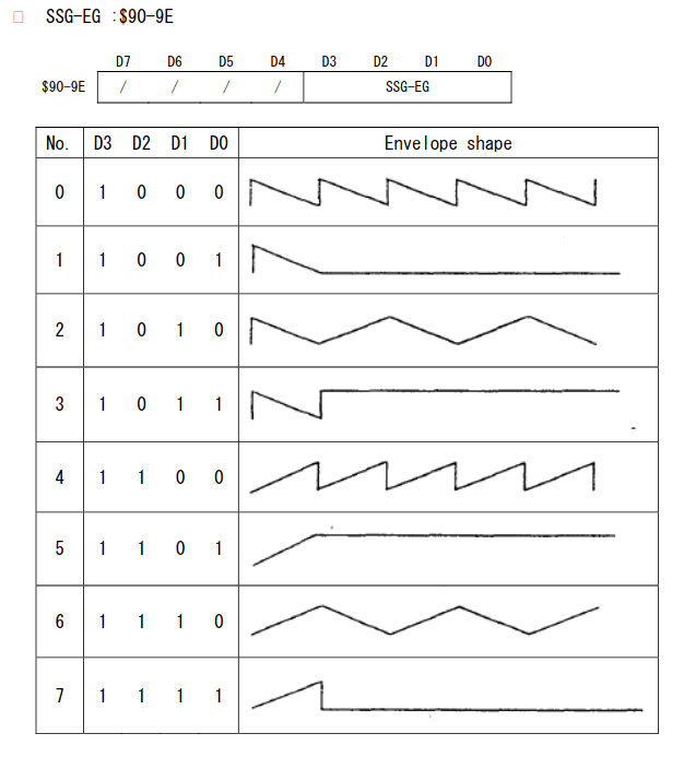 SSG-EG envelopes, from the YM2608 manual
The YM2612 still having SSG-EG functionality was completely undocumented officially, but that didn’t stop a handful of games from using it! Alisia Dragoon is the most well-known game I know of that uses SSG-EG, though from my testing SSG-EG emulation barely makes any audible difference in that particular game. There are other games where SSG-EG emulation does make a very noticeable difference, such as Ghostbusters.
This post will not cover how SSG-EG works. I may do so in a later post. EDIT: Here
Clock
The envelope generators clock one-third as frequently as the phase generators, so every third generated sample, or every 72 internal YM2612 cycles. This is an update rate of roughly 7.67 MHz / 144 / 3.
…Unless SSG-EG mode is enabled, since SSG-EG updates at the same rate as the phase generator clock (7.67 MHz / 144). However, even in SSG-EG mode, the normal envelope update logic only runs once every three phase generator clocks.
ADSR Transitions
The ADSR transition logic is fairly straightforward, but games are sensitive to getting it exactly correct.
First, note that keying on an already keyed-on operator has no effect, and same for keying off an already keyed-off operator. This is true for both the phase generator and the envelope generator: The key on/off logic should only apply when the operator changes from keyed off to keyed on or vice versa. Keying off happens to be an idempotent operation when SSG-EG mode is not implemented, but SSG-EG makes keying off non-idempotent. Keying on is never idempotent.
All future references to “keying on” or “keying off” are referring to the key on/off state changing, not just writing to register $28 with the appropriate bit set or clear.
Keying on an operator immediately changes the envelope generator from Release phase to Attack phase.
When in Attack phase and attenuation is 0, the envelope generator automatically transitions to Decay phase. This happens immediately, even if the envelope did not perform a single update in Attack phase! Some games depend on this.
When in Decay phase and attenuation is at or above the sustain level, the envelope generator automatically transitions to Sustain phase. This similarly happens immediately even if there were no envelope updates in Decay phase. Once in Sustain phase, the envelope remains there indefinitely until it is keyed off.
The configured sustain level is a 4-bit value that represents an attenuation in steps of 32, except for the highest sustain level (15) which is special cased to be the highest possible multiple of 32 (0x3E0 / 992).
Keying off an operator immediately changes the envelope generator to Release phase, regardless of what phase it was in before.
Note that keying an operator on or off does not immediately affect current attenuation level, except in one special case where keying on an operator with a very high attack rate causes attenuation to immediately drop to 0 (discussed in more detail in the Change Logic: Attack section). Upon key on, Attack phase begins decreasing attenuation from wherever it was before. Upon key off, Release phase begins increasing attenuation from wherever it was before.
To stub this out:
|
|
It is possible for both Attack and Decay phases to be skipped! Attack is skipped if an operator is keyed on while attenuation is already 0, and Decay is skipped if sustain level is 0. There are games that depend on emulating this correctly.
Key Scaling
Before describing the envelope update logic, it’s necessary to describe key scaling because it’s an important input to the update algorithm.
Key scaling is a feature that automatically adjusts the envelope change rate based on frequency, such that envelopes will change attenuation at a higher rate for waves playing at higher frequencies. Key scaling is always enabled, but software can adjust the level of key scaling using a 2-bit value configured in registers $50-$5F.
The key scaling process first computes a 5-bit key code value based on the phase generator’s F-number and block, the exact same key code that the phase generator uses to apply detune. Here is the key code calculation again, for convenience:
Bits 4-2 = Block
Bit 1 = F11
Bit 0 = (F11 & (F10 | F9 | F8)) | (!F11 & F10 & F9 & F8)
This 5-bit key code is then right shifted by (3-K), where K is the operator’s 2-bit key scale level, and the right-shifted key code is used to increase the envelope’s change rate. The range of possible values is 0-3 if key scale level is 0, and 0-31 if key scale level is 3.
This is the relevant formula from the YM2608 manual (for R ≠ 0):
Rate = 2R + Rks
Where R is the attack/decay/sustain/release rate of the current ADSR phase, and Rks is the right-shifted key code.
If R is 0 then Rate is always 0, Rks is ignored. It is fairly common for sustain rate to be 0, for example, which means that in Sustain phase the envelope generator should hold attenuation constant until it is keyed off.
This Rate value is what ultimately controls the envelope change rate.
Rate is a 6-bit value, clamped to the range [0, 63]. The max R value is 31, so 2R + Rks can exceed 63 if Rks is 2 or higher. Any such value is clamped to 63, the highest envelope change rate.
For Attack, Decay, and Sustain phases, the 5-bit attack/decay/sustain rate is used directly as R:
Rattack = attack_rate
Rdecay = decay_rate
Rsustain = sustain_rate
However, release rate is only a 4-bit value. Release phase computes R as:
Rrelease = 2 * release_rate + 1
This implies that R will never be 0 in Release phase, regardless of the configured release rate.
Change Rate
The envelope change rate logic is identical for all four ADSR phases. The only difference between phases is how R is computed, described in the previous section.
Change rate is determined by the Rate value described above, 2R + Rks, ranging from 0 to 63. This Rate is used in combination with a global envelope cycle counter and some lookup tables to determine both how frequently the envelope updates and the magnitude of each update.
First, the update frequency. The posts in the spritesmind thread describe this using a lookup table, but the logic is simple enough that you don’t need a lookup table for this.
Suppose you have a global cycle counter that increments once every envelope update cycle, so once every 3 phase generator updates or every 72 internal cycles. The chip uses bits in this counter to determine when individual envelope generators should update:
- Rate 0-3: Update every 211 global cycles
- Rate 4-7: Update every 210 global cycles
- Rate 8-11: Update every 29 global cycles
- …
- Rate 40-43: Update every 21 global cycles
- Rate 44-63: Update every global cycle
There is a pretty clear pattern there. The pattern terminates at 20 - with a Rate of 44 or higher, the envelope updates on every global cycle.
You can compute the exponent as:
|
|
Since these are all powers of two, checking against the global envelope cycle counter is as simple as a few bitwise operations:
|
|
…However, this isn’t completely accurate to actual hardware.
Per the cycle-accurate OPN2 emulator Nuked-OPN2 by nukeykt, which is largely a direct translation of the hardware into C, the envelope cycle counter is limited to 12 bits and it skips 0 every time it overflows! So the global cycle counter increment should actually be something like this:
|
|
This implies that the actual update rates are:
- Rate 0-3: Update 1 time every 4095 global cycles
- Rate 4-7: Update 3 times every 4095 global cycles
- Rate 8-11: Update 7 times every 4095 global cycles
- Rate 12-15: Update 15 times every 4095 global cycles
- …
- Rate 40-43: Update 2047 times every 4095 global cycles
- Rate 44-63: Update every global cycle
This is a significant difference for lower rates and barely any difference for higher rates…on paper. In practice it doesn’t make a huge difference either way because the counter 0 update doesn’t actually modify the envelope attenuation value unless the rate is 48 or higher (see the table below). The main effect of this skip-0 behavior is that envelopes update very slightly faster than they would without this behavior.
Now for the update magnitude. Here it’s a little cleaner to use a lookup table I think - otherwise you need a few special cases around the higher rates.
I don’t believe this is exactly how it’s implemented in the chip, but you can emulate this using a 64x8 lookup table that’s indexed into using the 6-bit Rate first and then the next 3 bits of the global cycle counter. In other words, the Rate determines a pattern of 8 values that the envelope generator steps through each time it updates.
Supposing the lookup table is a &[[u8; 8]; 64], the lookup logic is pretty simple:
|
|
One thing to note here is that if shift is higher than 9, as it is for rates 0-7, global_cycles >> shift will produce fewer than 3 bits since the cycle counter is 12-bit. This is correct behavior: rates 0-3 only use the highest bit of the cycle counter for the lookup, and rates 4-7 only use the highest 2 bits. Though it doesn’t make a behavioral difference given the table below.
The actual lookup table is…well, it’s just a table that’s been reverse engineered from the hardware. Here’s the relevant post in the big spritesmind thread: https://gendev.spritesmind.net/forum/viewtopic.php?p=5716#p5716
Here’s a formatted version that splits each group of 8 values into its own nested array:
|
|
The increment value is always either 0 or 1 for rates that update less frequently than once every global cycle. The maximum possible increment value is 8, which is used for every update at the highest rate values of 60-63.
Change Logic: Attack
Attenuation decreases exponentially during Attack phase, meaning that it decreases very quickly when attenuation is high and more slowly as attenuation approaches 0.
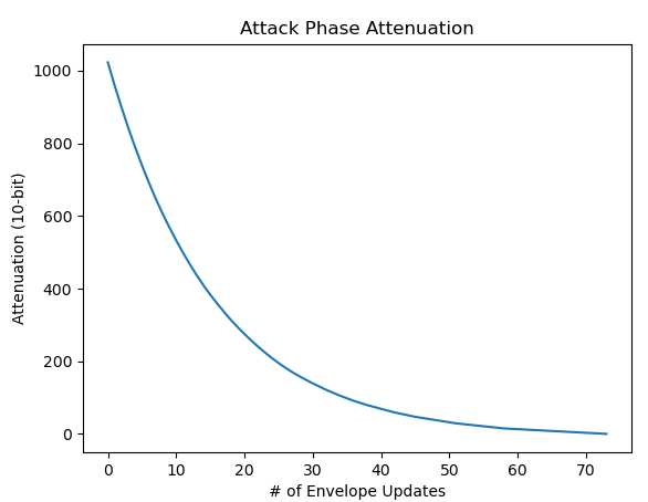 Attenuation curve with envelope increment 1
Once you’ve determined whether to update the envelope and what increment value to use, the actual update calculation is not too bad. Given current attenuation A and envelope increment I, the new attenuation A’ is:
A' = A + ((I * -(A + 1)) >> 4)
-(A + 1) is just the 1’s complement of A, i.e. flipping all the bits. So this is equivalent to:
A' = A + ((I * !A) >> 4)
Given that I is always either 0 or a power of two, this is almost certainly implemented in the chip as a bit shift rather than a multiplication, but the end result is equivalent.
Using >> 4 instead of / 16 is very important! A negative number will never right shift to 0, and the update logic depends on this fact for the attenuation to be able to reach 0 and end Attack phase.
There are two quirks with Attack phase and very high rates, specifically Rates 62 and 63.
The first is that when the Rate is 62 or 63, the envelope generator skips Attack phase entirely. This is implemented by checking the Rate at key on: if Rate is 62 or 63 at key on (calculated using Rattack), attenuation is immediately set to 0. At the next envelope update cycle, it will see that attenuation is 0 and automatically transition to Decay phase. There are games that depend on emulating this correctly!
The second quirk is that Rates 62 and 63 in Attack phase seem to skip attenuation updates entirely, so the envelope generator indefinitely holds the attenuation constant if it is not 0. The envelope normally skips Attack phase entirely if Rate is 62 or 63 by setting attenuation to 0 at key on, but it can get into this state if software increases attack rate, key scale level, or frequency after keying on but before attenuation reaches 0. I’m not aware of any games that depend on emulating this quirk, but the behavior has been verified on actual hardware.
Change Logic: Decay/Sustain/Release
Decay, Sustain, and Release phases all behave identically, linearly increasing attenuation. They’re also much simpler than Attack phase.
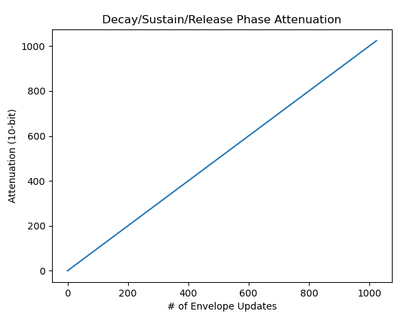 Attenuation curve with envelope increment 1
Given attenuation A and envelope increment I, the new attenuation A’ is:
A' = min(A + I, 0x3FF)
That’s it! The envelope generator adds the increment to attenuation, clamping to the maximum possible attenuation value.
Total Level
Finally, total level, which functions as a base attenuation level for each operator. Total level is a 7-bit value that specifies attenuation in steps of 8.
Total level does not affect the described envelope generation logic at all. It’s simply added to the envelope generator’s output during operator output calculations, clamping to maximum possible attenuation:
|
|
I’m not going to discuss tremolo / LFO AM in detail until a later post on the LFO, but it works kind of similarly in that it does not directly affect envelope generation logic - it adds attenuation to the envelope generator’s output, using the LFO to automatically vary the amount of added attenuation over time.
Summary
That is a lot of details. In summary, envelope generation works like so:
Each envelope generator has four phases: Attack, Decay, Sustain, and Release. Keying on puts the envelope in Attack phase and keying off puts the envelope in Release phase.
Attack phase exponentially decreases attenuation while Decay, Sustain, and Release phases linearly increase attenuation. The envelope automatically transitions from Attack to Decay when attenuation reaches 0, and it automatically transitions from Decay to Sustain when attenuation reaches the configured sustain level.
The envelope update rate is calculated using a combination of the current ADSR phase rate R and a key scaling factor Rks, the latter derived from key scale level and the phase generator’s frequency. This 6-bit rate value determines both how frequently the envelope updates and the magnitude of the attenuation change at each update.
Rates 62 and 63 during Attack phase are special in that they cause attenuation to immediately change to 0 at key on. Aside from this, keying on or keying off does not immediately affect attenuation level.
When the envelope updates during Attack phase, it subtracts a fraction of the current attenuation from itself, using the envelope increment as a multiplier. Decay/Sustain/Release envelope updates all add the envelope increment to the current attenuation.
Finally, total level is a constant base level of attenuation that gets added to the final envelope generator output during operator output calculations.
Operator Output V0.1
While not accurate to how the chip implements attenuation, if you wanted to test this out to hear what it sounds like, it’s not too hard to hack in floating-point attenuation calculations to the example code from Part 2.
Similar to that, this is not necessary as it is 100% throwaway code. It’s only to test out the envelope generator implementation before operator output is properly emulated.
Here’s the relevant part of the code:
|
|
And then you can remove the constant 0.3 “volume” multiplier when summing channel outputs.
This is actually kind of accurate in terms of what the chip is logically doing to compute individual operator outputs, but it’s very inaccurate in that it uses way more precision than actual hardware.
This produces audio that sounds slightly better. If nothing else, it removes the pops that were caused by keying operators on and off:
To Be Continued
The next post will cover how to properly compute operator and channel outputs, assuming that you have working phase and envelope generators (minus LFO-related functionality and SSG-EG). This will be enough to get audio working mostly correctly in some games!
EDIT(2025-03-30): Corrected some inaccurate information in the Change Rate section related to the global cycle counter, plus a minor inaccuracy regarding max sustain level