As with some/most of my previous posts, this is me writing something I wish I’d had when I started doing this: how can an emulator translate the audio samples generated by the emulated console audio hardware into something that the host computer’s audio device can play back, without compromising on audio quality?
This is most relevant for Game Boy [Color] and NES emulation, since both of those consoles internally generate audio signals at sample rates 1 or 2 orders of magnitude beyond what a typical PC audio device can play, but the general concepts apply to other systems as well.
You can probably find an audio or DSP library to do most/all of this for you. I wanted to learn how to do it myself, and this post is based on what I managed to cobble together for myself.
Sample Rates
To digitally emulate an audio chip, the emulated chip needs to output a stream of digital sample values at a specific sample rate, even if in actual hardware it outputs a continuous analog audio signal.
In some cases the chip has a clearly defined output sample rate, e.g. 32000 Hz for SNES (at least nominally) or 44100 Hz for PlayStation. From a sample rate perspective, these are the easiest to deal with because you can let your audio library and/or audio device handle everything for you! Create an audio playback stream with the same sample rate as the console’s native sample rate and just output samples as you generate them (though ideally pushing in small batches for performance reasons). Quality will depend on the audio library and device, but I’d expect that it’ll generally be at least decent.
Programmatic sound generation (PSG) chips don’t always have clearly defined output sample rates because they often output an analog audio signal rather than a discrete-time digital audio signal. Audio channels still usually generate digital samples internally, but the chip usually has its own DAC hardware (Digital-to-Analog Conversion) so that chip outputs are fully analog. Console hardware integrating the audio chip doesn’t need to care what sample rate it uses internally if the output is a continuous analog signal.
An emulator does need to care because it needs to emulate the chip digitally, including any audio effects introduced by the chip’s DAC or other analog audio hardware.
The most straightforward way to handle this is to assume that the chip repeats each digital sample infinitely in between sample changes, and to use the lowest possible sample rate that can precisely capture all sample changes. By that I mean that sample value changes should only occur on exact sample boundaries in your sample rate, never between samples.
This ends up being easier than it sounds because the chip is ultimately clocked at a particular fixed frequency, and samples can only change at integer dividers of that frequency. In practice you can usually use a lower sample rate than the chip’s clock rate though, as long as it’s an integer multiple of every possible “sample change” frequency (not the wave frequency!).
This repeating samples assumption is not generally safe to make - for example, upsampling a 24000 Hz audio signal to 48000 Hz by duplicating every sample introduces audible audio artifacts that were not present in the original audio - but it is safe to make for these PSG chips as long as you’re not sampling at a rate higher than the chip’s clock rate.
Here are the rates you need to use for some of the consoles that I’m familiar with:
| Console | Sample rate | Sample rate clock source |
|---|---|---|
| Game Boy / Game Boy Color | 2097152 Hz | CPU T-cycle clock /2 (/4 in GBC double speed mode) |
| NES (NTSC) | 1789773 Hz | CPU clock |
| Sega Master System (NTSC) / Game Gear | 223721 Hz | CPU clock /16 |
| Sega Genesis (NTSC) - YM2612 chip | 53267 Hz | 68000 clock /144 (or master clock /1008) |
| Sega Genesis (NTSC) - SN76489 chip | 223721 Hz | Z80 clock /16 (or master clock /240) |
Yes, for NES you need to sample at the full clock rate to capture all possible sample changes. Blame the triangle channel.
YM2612 (Genesis) is slightly simplified because it assumes that you’re going to mix the 6 channels instead of multiplexing them, and that you’re going to emulate the 4 output slots by summing/averaging them rather than explicitly outputting each slot. The only emulator I’m aware of that actually emulates the multiplexing + output slots is the cycle-accurate Nuked-OPN2. If you want to do cycle-accurate emulation then you need to sample at 1278409 Hz (68K clock /6).
The (simplified) YM2612 at 53267 Hz isn’t too bad since you can let the audio device resample for you, but these other sample rates are high enough to potentially pose a problem. You might be able to output 223721 Hz samples directly, but you almost definitely will not be able to do that with the 7-digit sample rates of GB and NES. The emulator needs to do something in software to convert those audio signals to a lower sample rate for audio output.
Resampling
Let’s start with the most naive possible resampling implementation: whenever an output sample is needed, output the most recent input sample.
Given a source sample rate S and a target sample rate T, each input sample at S should result in T/S output samples. This ratio is not necessarily an integer (and usually won’t be).
You can track this with a counter:
|
|
You might want to prefer to use integer math instead, in which case you can treat the counter as units of 1/S to avoid the division:
|
|
And…you have a functional audio resampler! Not a good one (quite bad actually), but functional!
Here are a few examples from different systems of why this is not a good resampling implementation:
These are all resampling to 48000 Hz from the sample rates listed above. Yes, even resampling from 53267 Hz to 48000 Hz this way can cause erroneous noises like in the Batman & Robin example.
Resampling this way introduces extremely significant audio aliasing. When downsampling using a poor implementation (e.g. the one above), high-frequency waves in the source audio can cause audible ringing or buzzing noises in the downsampled signal, plus this causes the downsampled signal to generally sound harsher than it’s supposed to.
This is what those are supposed to sound like:
Although that last one sounds much more like this on actual hardware due to the Genesis hardware low-pass filter:
Speaking of low-pass filtering, that’s really the ideal way to solve this: apply a low-pass filter to the source signal to remove all waves below the target sample rate’s Nyquist frequency (half the sample rate), then interpolate between low-pass filtered input samples to produce output samples. For downsampling from 7-digit sample rates to 48000 Hz, basic 2-point linear interpolation (i.e. weighted average of the 2 nearest samples) is good enough assuming the low-pass filter does its job.
Isn’t There an Easier Way?
Well…kind of! Not for Genesis though, the audio synthesis is way too complicated.
If you just want to eliminate the most obvious ringing/buzzing noises, you can silence audio channels when they’re generating waves at frequencies above 20000 Hz or so. “Silence” meaning that you have the channel output a constant sample value rather than oscillating at an ultrasonic frequency. 20000 Hz is generally considered the upper limit of the human-audible frequency range, and it’s below the Nyquist frequency of 48000 Hz.
Taking the NES triangle channel as an example: given a non-negative period P set by software, the channel generates a 32-step waveform where each step is held for (P+1) CPU clocks. So, the overall wave frequency is:
|
|
Set freq to 20000 and solve for P and you get roughly 1.797. So, you can silence the channel when P is 0 or 1 to prevent it from generating ultrasonic triangle waves.
(Some NES emulators offer this particular option as an optional audio enhancement because, aliasing aside, doing this significantly reduces audio popping in some games.)
This doesn’t remove all high-frequency wave components from the signal though, because you need high-frequency sine waves to construct sharp waveforms like pulse waves. You’re still going to have audio aliasing in the downsampled signal, it just won’t be quite as bad.
A (Relatively) Simple Low-Pass Filter
There is not really a best way to low-pass filter because there are numerous tradeoffs around filter behavior and runtime performance. I’m going to describe a way to make and use a filter, but you’ll probably want to experiment a little to see what works well for your preferences.
I’m not going to go into detail on the math involved, but every audio waveform (and more generally every periodic function) can be decomposed into an infinite sum of sine waves at different frequencies and phases. A digital signal at sample rate N can only contain sine waves of frequencies N/2 or lower (the Nyquist frequency) without introducing audio aliasing, so when downsampling to a frequency FT, you need to remove all sine waves at frequencies above FT/2 as part of the downsampling process if you don’t want aliasing.
An ideal low-pass filter passes all waves below the cutoff frequency Fc and completely removes all waves above Fc. The ideal low-pass filter is impossible to implement in practice, so practical low-pass filters approximate the ideal response as best as possible.
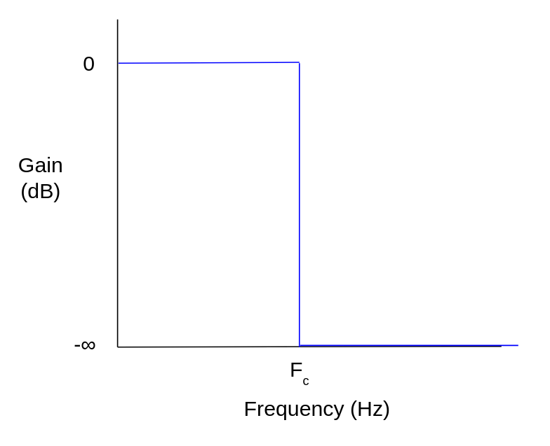 Ideal low-pass filter frequency response
There are many different ways to create such approximations. In this example I’m going to design and use a Chebyshev Type 2 IIR filter, aka an inverse Chebyshev filter. Chebyshev filters have a steep attenuation slope in the transition from the pass band (below cutoff frequency) to the stop band (where waves are “fully” attenuated), but in exchange they have ripple in either the pass band (Type 1 filters) or the stop band (Type 2). If you want a filter without ripple then you could design a Butterworth filter instead, though the attenuation slope won’t be as steep (given the same filter size).
Assuming your source frequency and target frequency are fixed, you can generate the filter offline using whatever tools you want and then hardcode the filter coefficients into your emulator. Applying a filter is much much simpler than designing one.
Here’s an example of how to design an inverse Chebyshev filter using Python and scipy. This designs a filter and prints the filter coefficients. You can run it using uv (uv run whatever.py):
|
|
fc here isn’t exactly the cutoff frequency - it’s the desired frequency where attenuation should first reach rs, i.e. the beginning of the stop band. See cheby2 docs. This varies by filter design algorithm - others do take the desired cutoff frequency as input.
sos output format is “second-order sections”, where higher-order filters are designed as a sequence of second-order filters rather than a single set of coefficients. This greatly helps avoid the numerical stability problems that can occur if you naively implement a higher-order IIR filter using 64-bit floating-point numbers. You need a higher-order filter to downsample GB or NES audio with decent quality, so this is very useful.
With those particular parameters, I get these coefficients:
[0.009672154480534816, -0.019108473927772984, 0.009672154480534814, 1.0, -1.940218848857816, 0.9413084433331829]
[1.0, -1.9957953252395741, 1.0, 1.0, -1.9787845588378847, 0.9796946310111055]
It’s extremely helpful to get an idea of how the filter will perform before you’ve integrated it. You can use freqz to compute the filter’s response in the frequency domain, then use something like matplotlib to plot it:
|
|
Here’s the frequency response of the above 4th-order filter:
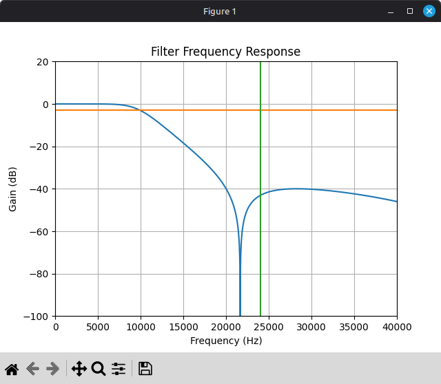
You probably don’t actually want to use this filter. It starts attenuating pretty heavily around 10000 Hz, so it’s going to audibly soften the audio, plus you might want higher stop band attenuation than 40 dB. But, it’s something to start with. You can adjust the parameters and see how they affect the filter frequency response, as well as the final output sound in the emulator.
An IIR filter of order N has two sets of N+1 coefficients: feedforward coefficients b and feedback coefficients a, where the feedforward coefficients apply to input samples and the feedback coefficients apply to previous output samples. With sos output format, you get an array of 6-element arrays that each contain the 6 coefficients for a second-order filter: first the 3 feedforward coefficients from b0 to b2, then the 3 feedback coefficients from a0 to a2. a0 should always be 1.
Once you have the coefficients, applying a second-order IIR filter is pretty straightforward. Generic application of an Nth-order IIR filter looks something like this, where x is input samples and y is filter outputs, both ordered from oldest to newest:
|
|
For second-order specifically:
|
|
For a higher-order filter in second-order sections format, you’ll have a series of second-order filters that you need to apply in sequence:
|
|
And that’s a somewhat decent low-pass filter implementation! …With one big caveat: denormals can wreck your performance, particularly on Intel CPUs. IIR filters are highly prone to getting stuck at a denormal value when they should decay to zero. In the context of audio, this often happens during periods of silence where all input samples are zero.
In the interest of staying language-agnostic and hardware-agnostic, this blog post describes a branchless trick that you can use to avoid your IIR filters getting stuck at denormal values when they should decay to zero: https://www.earlevel.com/main/2019/04/19/floating-point-denormals/
In C/C++ on x86, you can use GCC’s -funsafe-math-optimizations flag to make the CPU automatically convert denormals to zero, though this can cause other problems (the optimizations are not always fun and safe).
In Rust, you can technically modify the x86 floating-point environment by manually loading into the MXCSR register, but it’s unclear to me whether doing so violates compiler assumptions and causes undefined behavior. I wouldn’t recommend doing it.
FTZ and DAZ really should have been opcode bits rather than global per-thread CPU state, but alas. This is a tangent.
Even if you’re avoiding/handling denormals, applying a filter like this to a high source frequency (e.g. GB/NES) can be somewhat computationally expensive. Modern CPUs can easily handle it, but you may want to perform audio resampling in its own thread so that it can run in parallel to the actual hardware emulation. Passing samples between threads isn’t too expensive if you use some sort of lock-free ring buffer and push samples in batches.
Interpolation
Once you’ve applied a low-pass filter to the source audio, you can use the naive resampling implementation above on the low-pass filtered signal, and it will actually produce somewhat decent results! But it’s not hard to do a little better.
Whatever interpolation algorithm you want to use will require tracking the current distance between input samples. You can modify the naive implementation above to track this using a separate counter, and to only advance through the input stream when this counter decrements. Given source rate S and target rate T, each output sample should cover exactly S/T input samples:
|
|
This assumes that you always have at least 2 input samples available (and that you’re using an interpolation algorithm that only requires 2 samples). You can accomplish this in a few ways, e.g. by prefilling input_samples with 2 zero samples during initialization.
Assuming we’re downsampling a low-pass filtered source signal with a very high S/T ratio, 2-point linear interpolation works well enough:
|
|
For upsampling you’d want to do something fancier, but upsampling is also much less of a problem in general because you can let your audio device do it for you. You might also want to do something fancier if the S/T ratio is not as large.
Integrating this for Game Boy with the 4th-order filter above produces this, with the other versions for comparison:
Yeah, this is pretty bad, but that was expected based on the filter frequency response plot. This low-pass filter attenuates the ringing but it’s still audible, plus the filter significantly softens the audio. Pulse waves should be clear and sharp!
That’s not inherent to the filter method though, just the way that particular filter was designed. Here’s the filter frequency response plot for a different inverse Chebyshev filter:
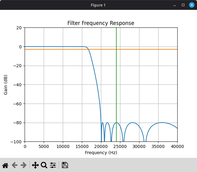
This filter is 16th-order instead of 4th-order, and it targets a higher stop band attenuation.
Here’s with that filter in place of the other one:
Much better! At least I think so.
Of course, this isn’t free. Applying a 16th-order IIR filter to a 2097152 Hz signal is very expensive. Not so expensive that you can’t do it in real time, but it’s something to be aware of.
For another example, here’s a song that doesn’t have several seconds of silence at the beginning (though also not nearly as much ringing to begin with):
Alternative Approaches
You could try designing and using a FIR low-pass filter instead of IIR. You will need a significantly higher filter order to achieve comparable results, but it’s also very easy to vectorize FIR filter application using SIMD instructions since FIR filters have no feedback, so you may get better runtime performance even with a much larger filter (assuming you vectorize the filter code yourself, compilers don’t like to auto-vectorize floating-point arithmetic too much).
Another approach is windowed sinc interpolation, which I used in some of the examples above. This algorithm along with the math behind it is described here: https://ccrma.stanford.edu/~jos/resample/resample.html
The core idea behind this algorithm is to upsample the source signal by a huge integer factor by padding it with zeroes, apply a massive FIR low-pass filter (i.e. a sinc kernel) to the upsampled signal, then linearly interpolate between low-pass filtered samples. The algorithm doesn’t perform exactly these steps because that would be horrendously inefficient, but logically this is what it’s doing. It can be performance-intensive depending on the upsample factor and the size of the sinc kernel, but the output quality is excellent. (This is what I personally use in my own emulators now.)
There’s also blargg’s Blip Buffer library (LGPL), which works extremely well if you decide that you’d rather not implement any of this yourself.